an automitive CAN Bus system for classic cars
Introduction
This is the very early stage of the development of a CAN Bus system for simple automotive purposes.
In the olden days, cars had hundreds of meters of cable in them, connecting switches – like the light switch – to lamps and motors – like the headlights and taillights – of your car. As cars became more complex, this simple logic would no longer work. As electronics became cheaper and more common in cars, Bosch introduced the CAN bus system in 1986 which was first put into a BMW 8 Series car in 1988. CAN is now standard on mandatory OBD-II systems in all cars built after 1996 in the U.S.,, since 2001 in Germany.
Picture from Wikipedia, Wikimedia Commons
After taking apart myVW Van from 1972 to convert into to an electric vehicle, it became quite apparent, that I would not be able to save the original wiring, and that it would make little sense to rewire the original setup. All of the combustion engine wiring was now obsolete anyway, and new wiring had to be introduced for battery management and speed control, plus many safety features that are required for an electric vehicle.
And while we were at it, why not add all the convenience features of a modern car: automatic vipers, automatic headlights, and hey, with radar systems available, why not add TACC and traffic sensitive high beams?
So the idea was born to convert the entire VW wiring from 1972 copper salad to 2016 CAN bus magic.
TODO:
High level list:
- topography:
- CAN Bus
- single low to medium speed CAN bus for light, switches, motor control, charge control, battery managemnt
- twisted wire has to run from the front to the back in a zigzag to reach every controller
- enough controllers to be safe (left tail light, right tail light, so if one fails, the other light will remain)
- central controller as pseudo master with peer-to-peer fallback
- Power Bus
- star shaped topology from the fuse box to one or more controllers per wire
- will we need an extra power supply for all controllers?
- extra ground wire?
- CAN Bus
- safety
- hardware
- automotive components
- compact and protected modules
- all modules are the same with optional power stage
- software
- watchdog system that falls into emergency mode if central controller fails
- “missing-module” procedure
- diagnostic system with tablet computer
- hardware
Low level list:
-
- decide for a controller
- LPC11C22 contains all components including the transceiver in a single powerful chip for under 4 Euros
- …
- decide for power inverter
- Protection->Bourns, CDSOT23-T12LC, TBU-CA065-100-WH, MOV-10D201K
- decide for peripheral controllers
- high side drivers for low and high amp lights
- MC33879 for example?
- driver for inductive loads (horn, wiper motor)
- RS232 communicator for BMS and Drive Controller
- multi input controller for dashboard and all buttons
- PWM output for servos to reuse analog instruments
- special inputs for light sensor, rain sensor, etc.
- special outputs, PWM, sound
- high side drivers for low and high amp lights
- all-in-one devices
- TLE9262QX for example?
- hardware
- cables and wiring
- connectors
- CiA Draft Recommendation DR-303-1
- Flachstecker auf Platine, FASTPM 187 PCB TAB TPBR, FASTON 187 PCB TAB TPBR, FASTON 205/250 PCB MOUNTED TPBR (6.3mm and 2.8mm)
- Schneidkrimpanschluss
- Printklemmen
- Klemmen für Litzen
- decide for a controller
- Crimp IPC (IPC: Insulation Piercing Connecor)
Lots to decide. Hey, I said that this is an early stage 😉
Size and Connectors
Let’s assume that we want to replace the basic automotive relais. They have two connectors to the coil and two or three contacts to the switch. The CAN bus variant requires two additional connectors for the bus.
These Relais have a footprint of 28mm x 28mm and are 25mm high or taller.
I want to make the modules themselves modular, so I decided to create a PCB as a base plate that is 28mm wide and varies in length, based on requirements, yet aiming at the standars 28mm for basic relais setups. The base plate holds all connectors except CAN.
Soldered vertiaclly onto the base board is a CPU board and as many input and output bards as needed for that module. The CPU module also holds the power regulator (if possible). The CAN connectors are on the top end of the CPU board.
Measurements: Relais
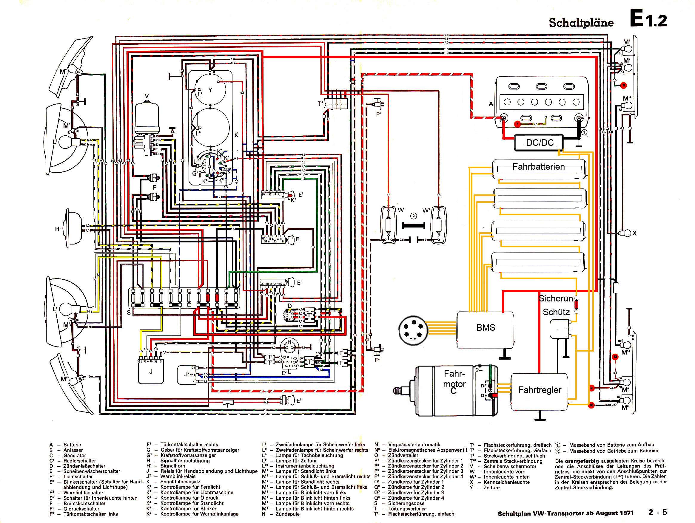
Kabelbaum (D)
Dies ist der Kabelbaum eines VW T2 Bus von 1971. Der Schaltplan reflektiert recht gut die Verlegung und die Geometrie.
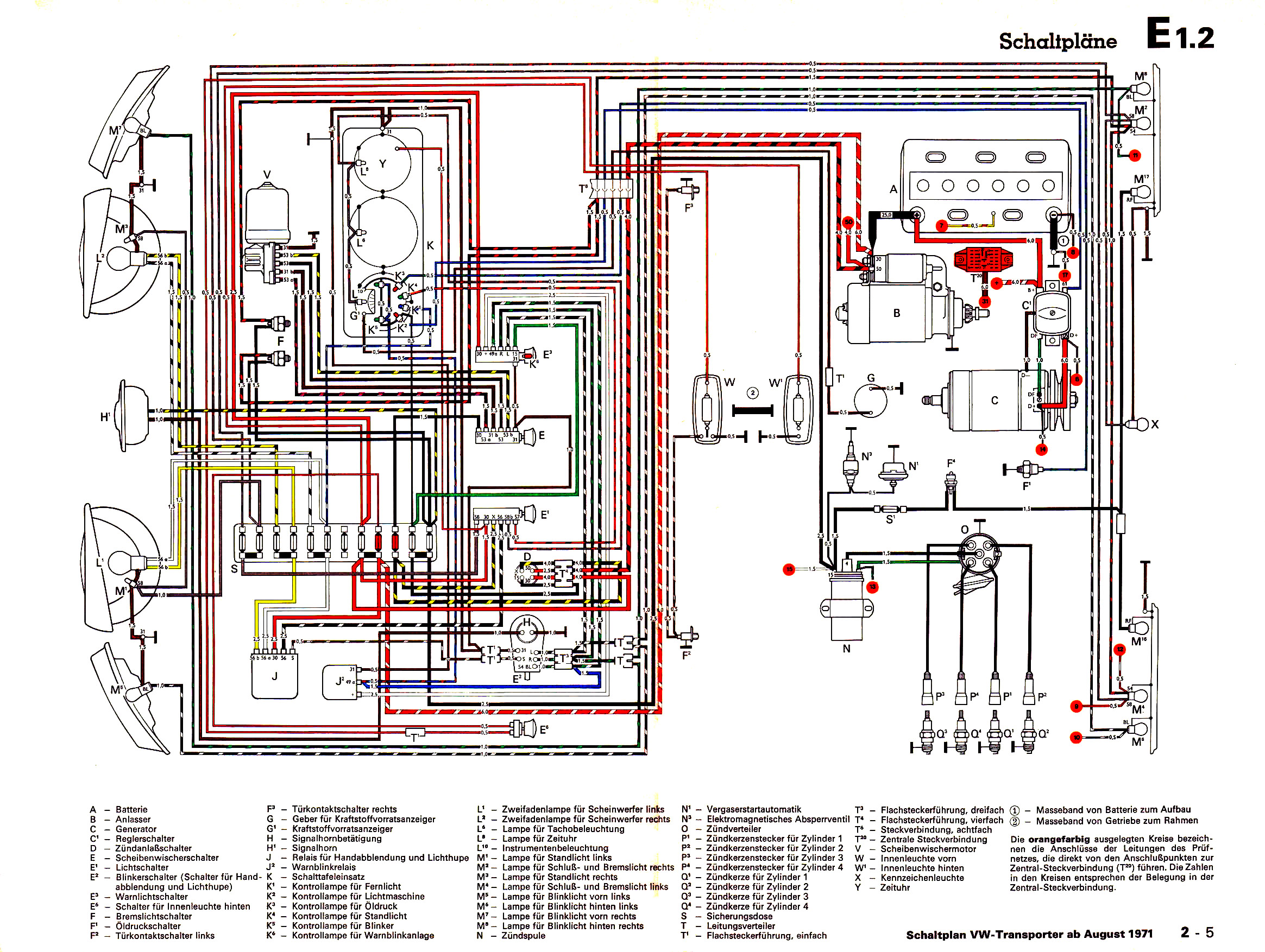
Aber trotzdem ist der Kabelbaum nicht ganz ehrlich, denn im Motorraum fehlen die Kabel zum Diagnosestecker. Das sähe dann so aus.
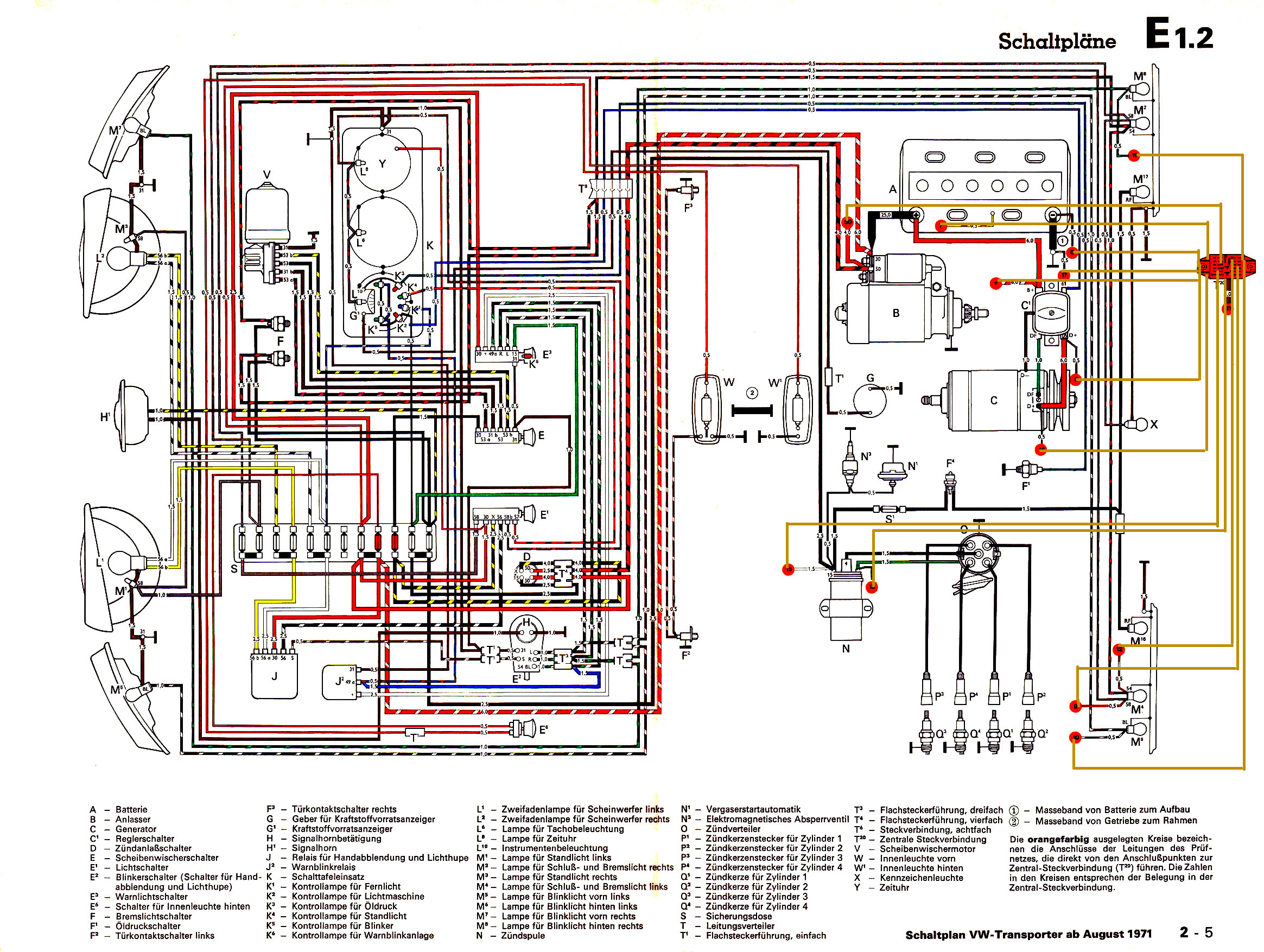
Jetzt schmeissen wir mal den Verbrenner raus und alle Kabel, die dafür benötigt werden. Das ist einiges übersichtlicher.
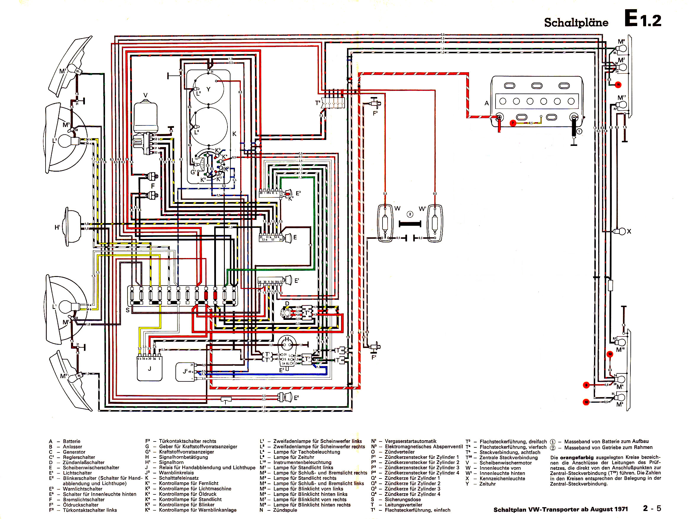
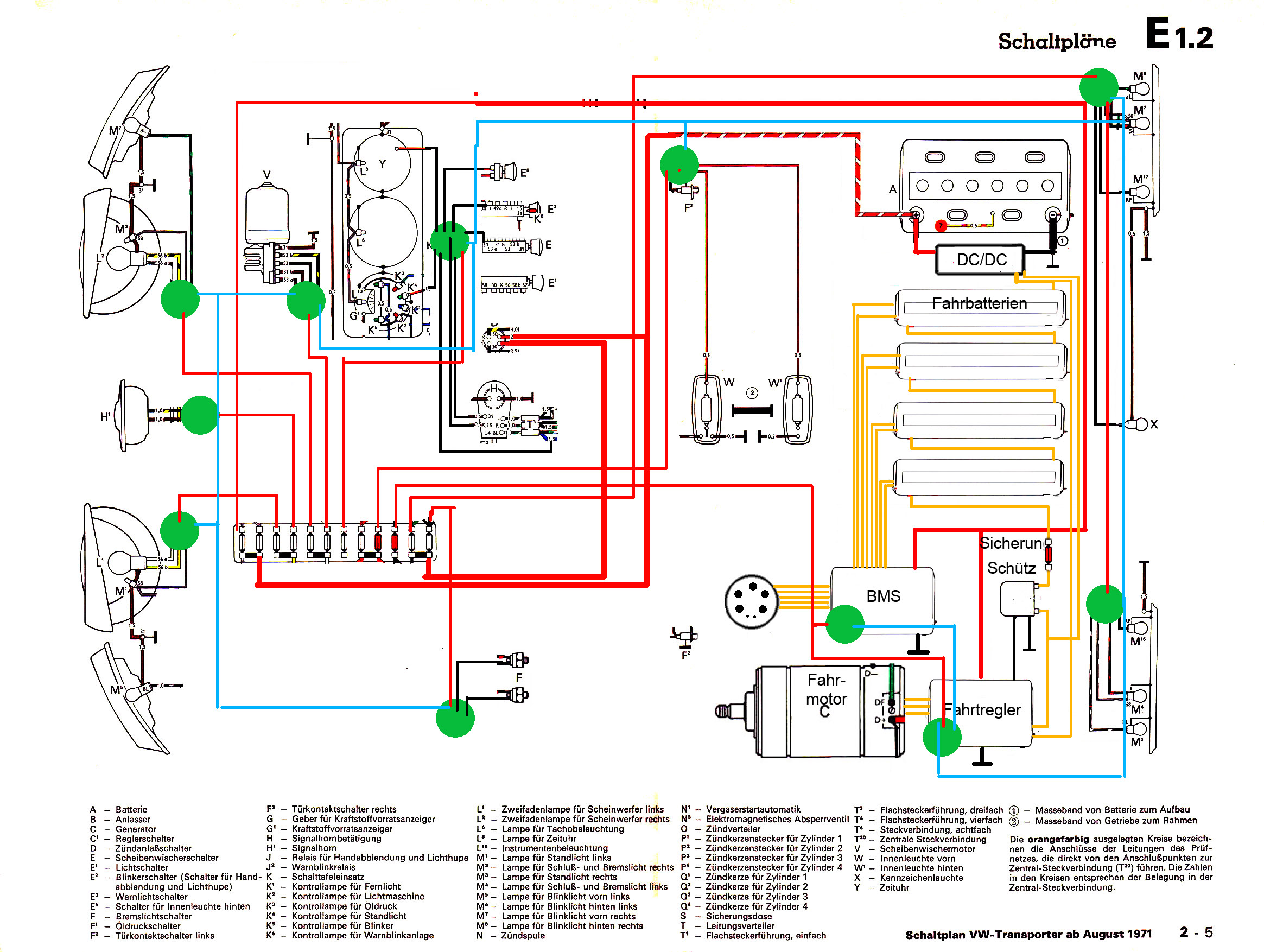
Aber wir wollen ja auch fahren können. Also rein mit dem Elektroantrieb. Leitungen in Orange führen 240V Wechselstrom oder 144V Gleichstrom, sind also mehrlagig und u.U. daumendick um Ströme bis zu 300A zu führen. Diese Leitungen sollten so kurz wie eben möglich sein, was beim VW Bus möglich ist, da die Batterie nah am Motor liegt.
Jetzt schmeissen wir mal die ganze konventionelle verkabelung raus und setzen CAN Module an strategische Stellen. Die grünen Kreise sind die CAN Module. Die hellblaue Linie ist der CAN-Bus, ein verdrilltes Kabelpaar.