
Building an 8, 16, and 35mm Film Scanner (Telecine) from scratch
What?

Remember film? That hundreds of meter long transparent strip with individual images printed on it? Shine a light through it, add a shutter, and you can project movies to wall. Fascinating, Isn’t it?
Why?
Digging through my Dad’s office and archive, I found a great number of films in 16mm format (1938 to 1964!). He has many more at home. It was hard enough to get a working 16mm projector, but watching the films was complicated and time consuming. It was smelly, too, especially after the projector blew a tar capacitor in the middle of the living room.
Obviously, I need to transfer those films to the PC and run them on an adequate HD screen.
How?
I digitized all films by pointing an old video camera at the silver screen, but the quality is terrible (as expected). Having them professionally digitized is out of the question (it would cost me thousands). So what’s more obvious than building my own film scanner? Nothing, right? 😉
Planning
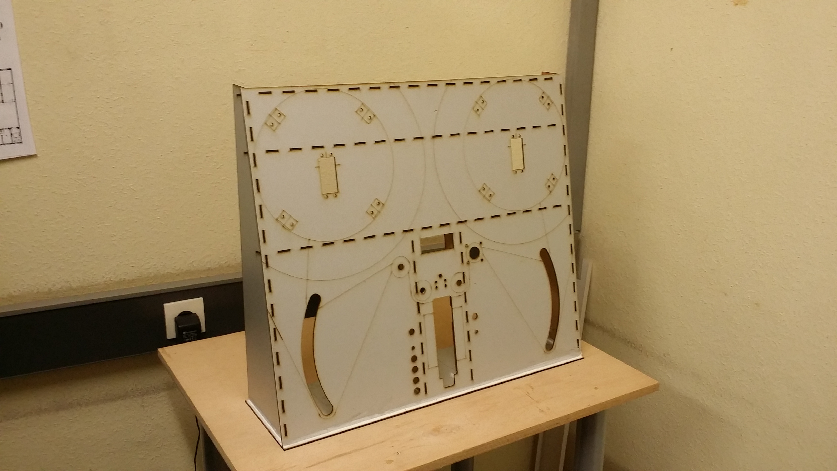
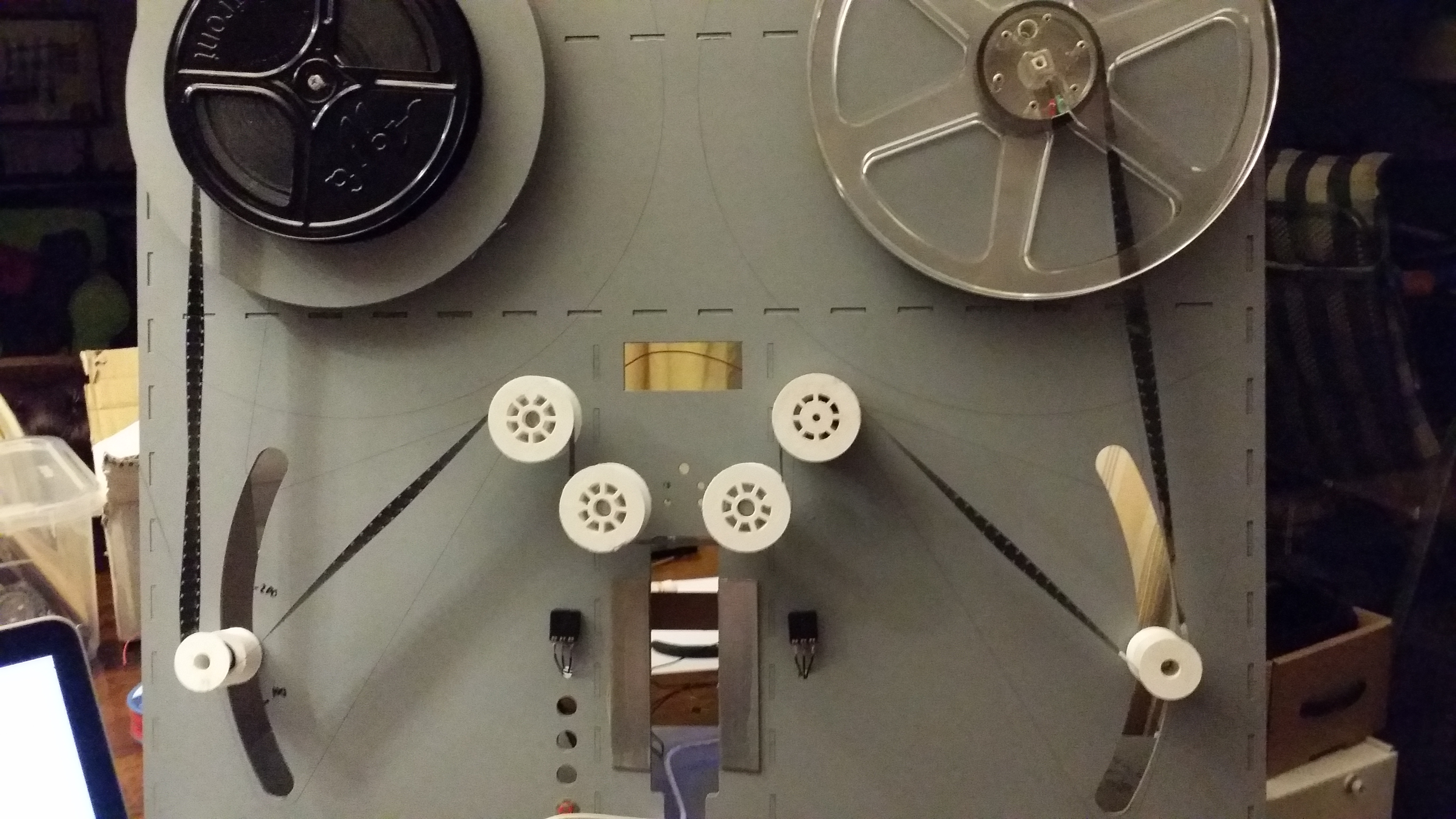
It’s not a perfect picture, but you should be able to see the lines and cut-outs. The machine is standing upright at a slight slant backwards to conserve desk space.
There is space for big reels at the top left and right. At the bottom left and right are two arms that keep the correct tension on the film automatically. In the middle are four more rollers for transport (one roller is connected to a stepper motor). An LED light shines from the top through the film into a digital microscope.
The microscope hast better than full HD resolution. Controlling the LED brightness, I can easily get a full HD image with HDR image data (12 bits per color!).
In Control
At the heart of the machine is an Arduino. It controls two quarter-scale servos that turn the reels, a stepper motor for transport, and a bunch of LEDs. Two potentiometers tell the microcontroller about the film tension. FOur buttons and a 2×16 display help the user to control the machine.
Inside the case is a power supply and a USB hub to hook up the Arduino and the Microscope. A host computer is needed to record images, but winding the film will be possible with the built-in controls.
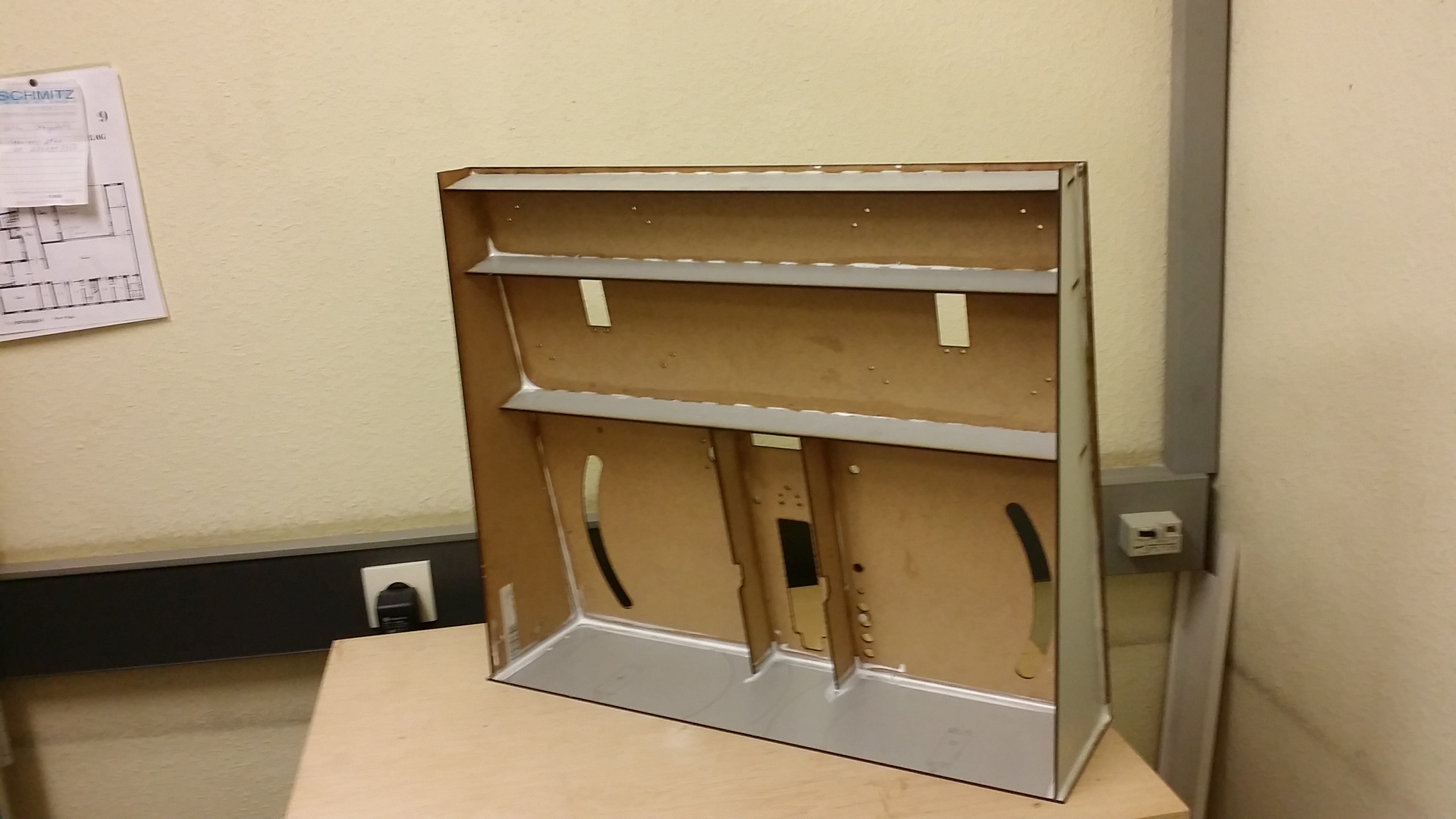
Back Cabinet
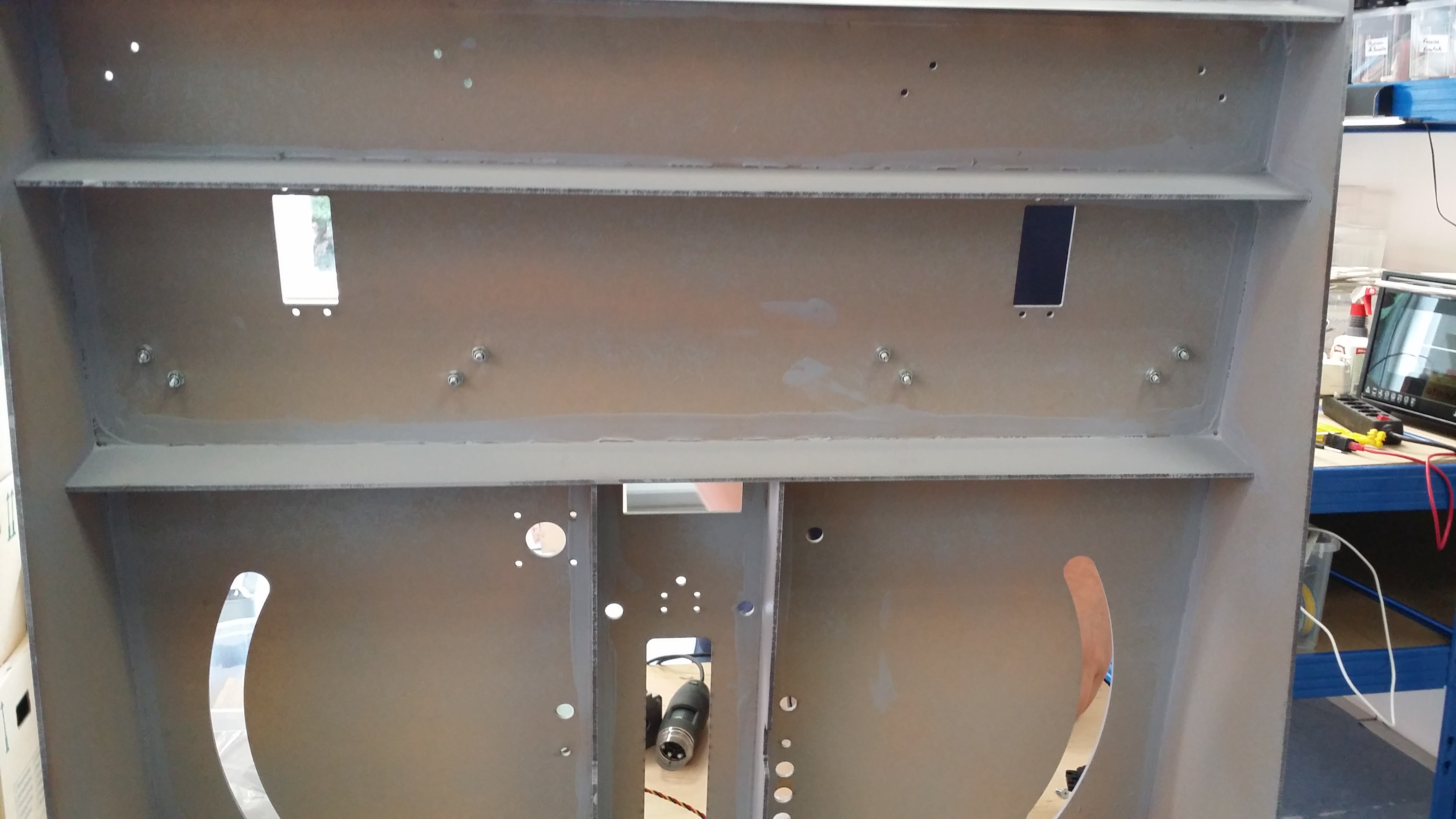
The back side of the case. There are some strips for reinforcement. The material is PVC-covered HD particleboard that was laser-cut. If the machine will work, I will publish improved CAD files for everything.
Endless Servo
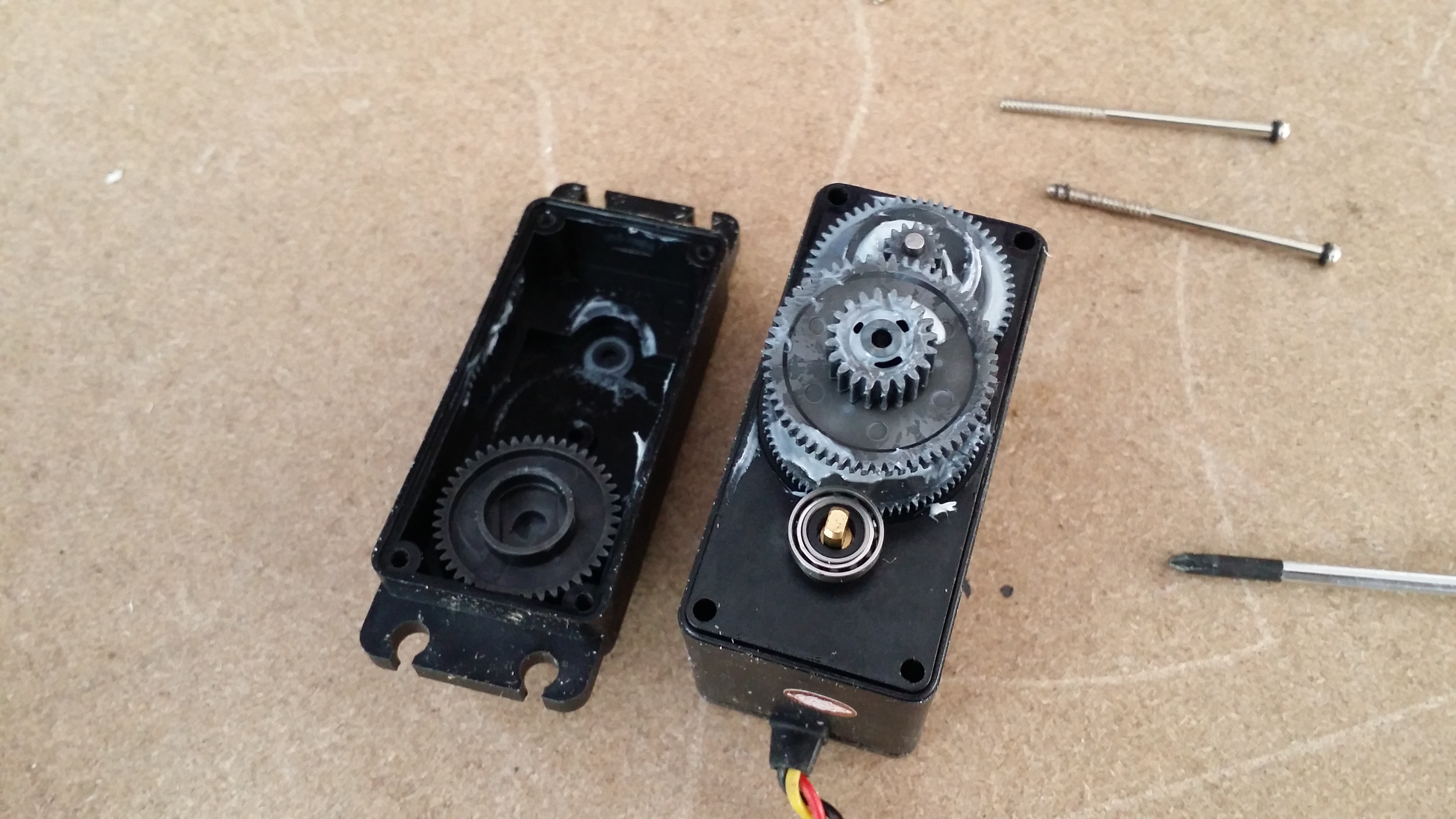
Before mounting the reel drive servos, they must be modified for continous rotation. This was very easy for the servos I used. The built-in potentiometer is controlled by a clip in the top gear that can be removed with a small screwdriver. This gear has a bar that keeps it from rotation all the way and destroying the pot.
Remove the plate and the bar. File down the edges, or the bar will grind on the stoppers.
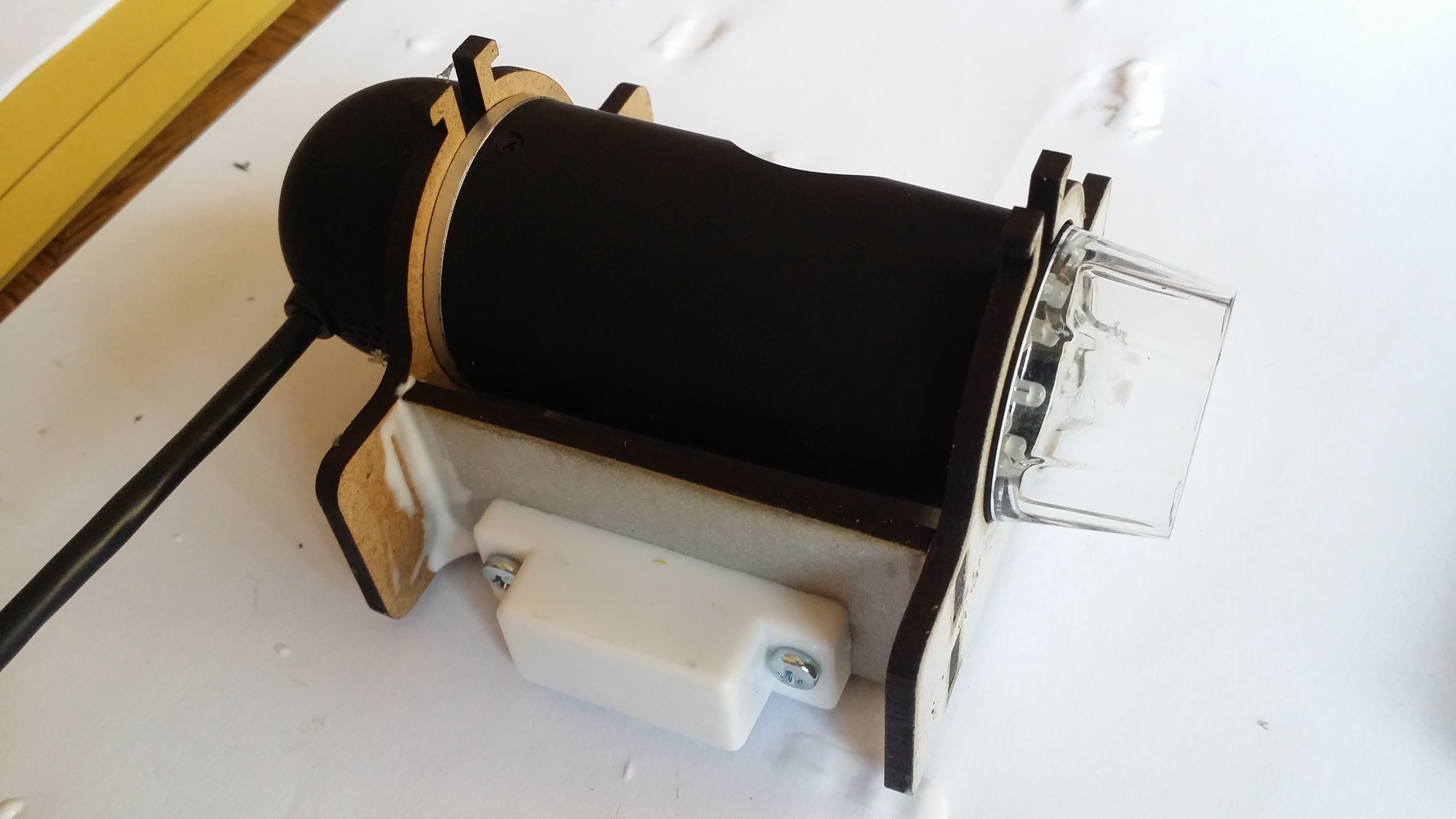
Reel Drive
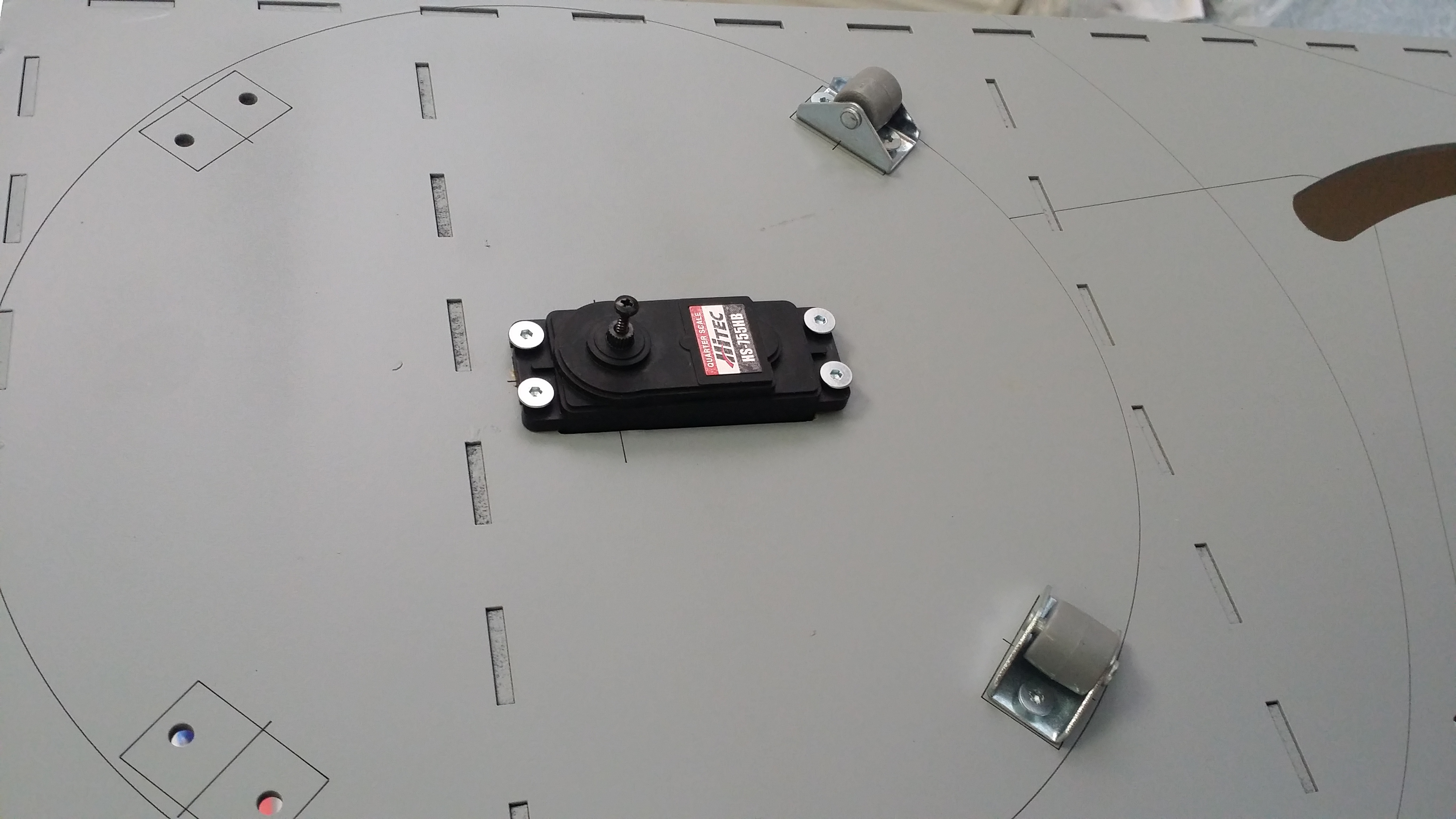
Here is the reel drive motor already mounted. This is a quarter-scale R/C servo that is modified for continuous rotation.
How does the tension thing work? Below the reels are arms that hold a loop of film. A spring pulls the arm down. If the loop get too loose, the reel motor will slow down to feed less film. If gets too tight, the motor will increase the feed. The receiving reel increase speed if the loop is too loose, and decreases speed when it is too tight.
This is a nicely self-controlling system. Running the film transport stepper at any direction or reasonable speed will change tension on the arms, which in turn will update reel motor speed.
This system is much nicer on the film than the slipping clutch in the film projector which puts an unpredictable tension on the film, especially when the clutch has aged and may stick or slip unpredictably.
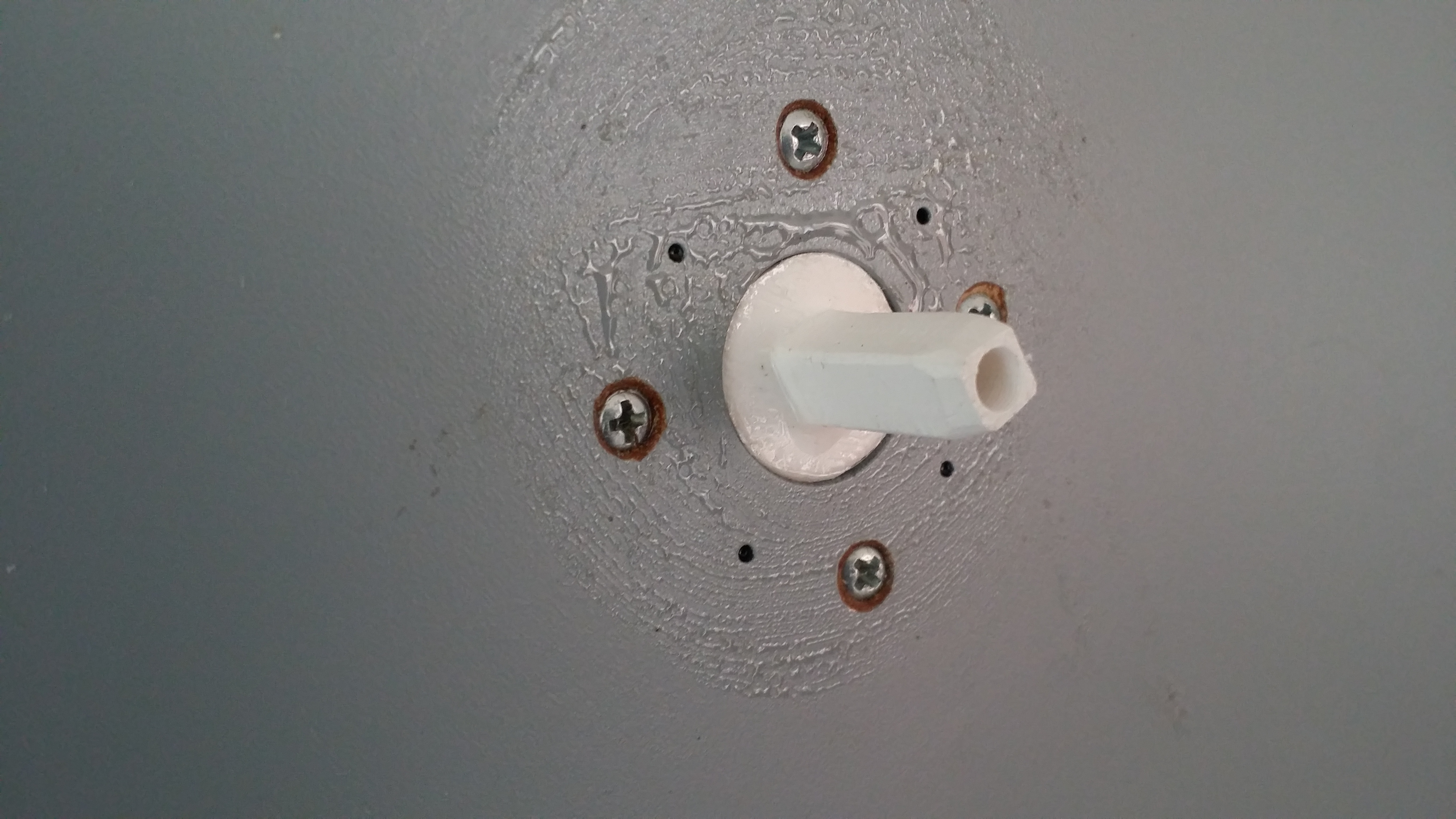
Reel Plate
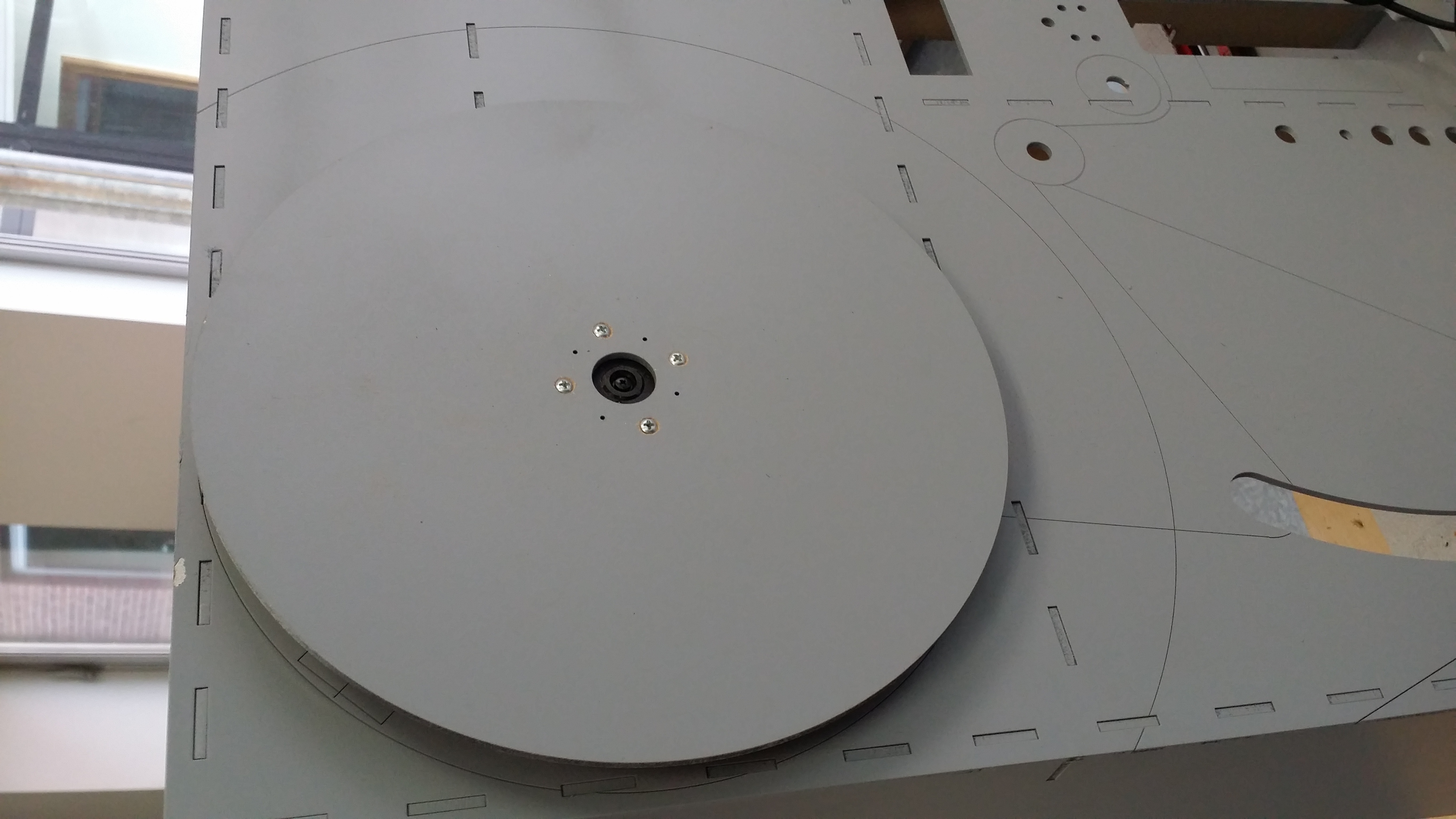
Here is the first reel plate mounted. The center hub printed in the 3D printer.
Reel Support
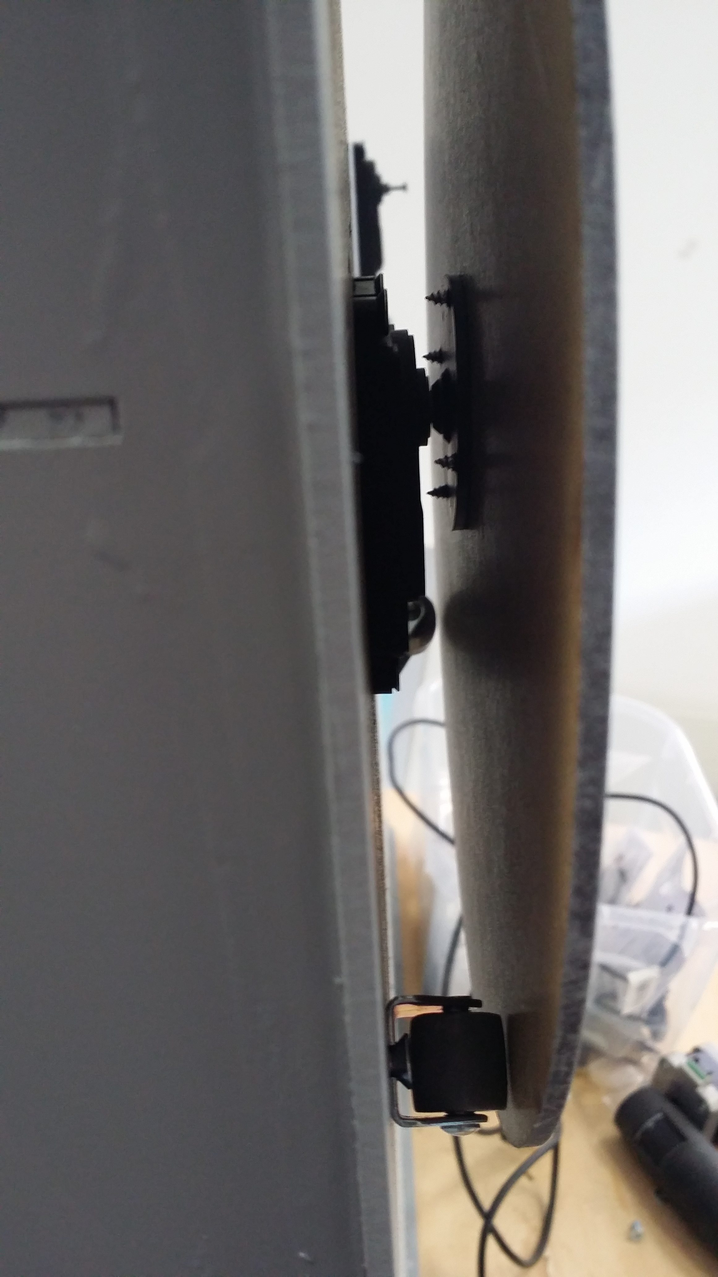
This is a view between case and reel plate. There is a roller visible at the bottom that helps taking load off the bearings in the servo.
Back of Reel
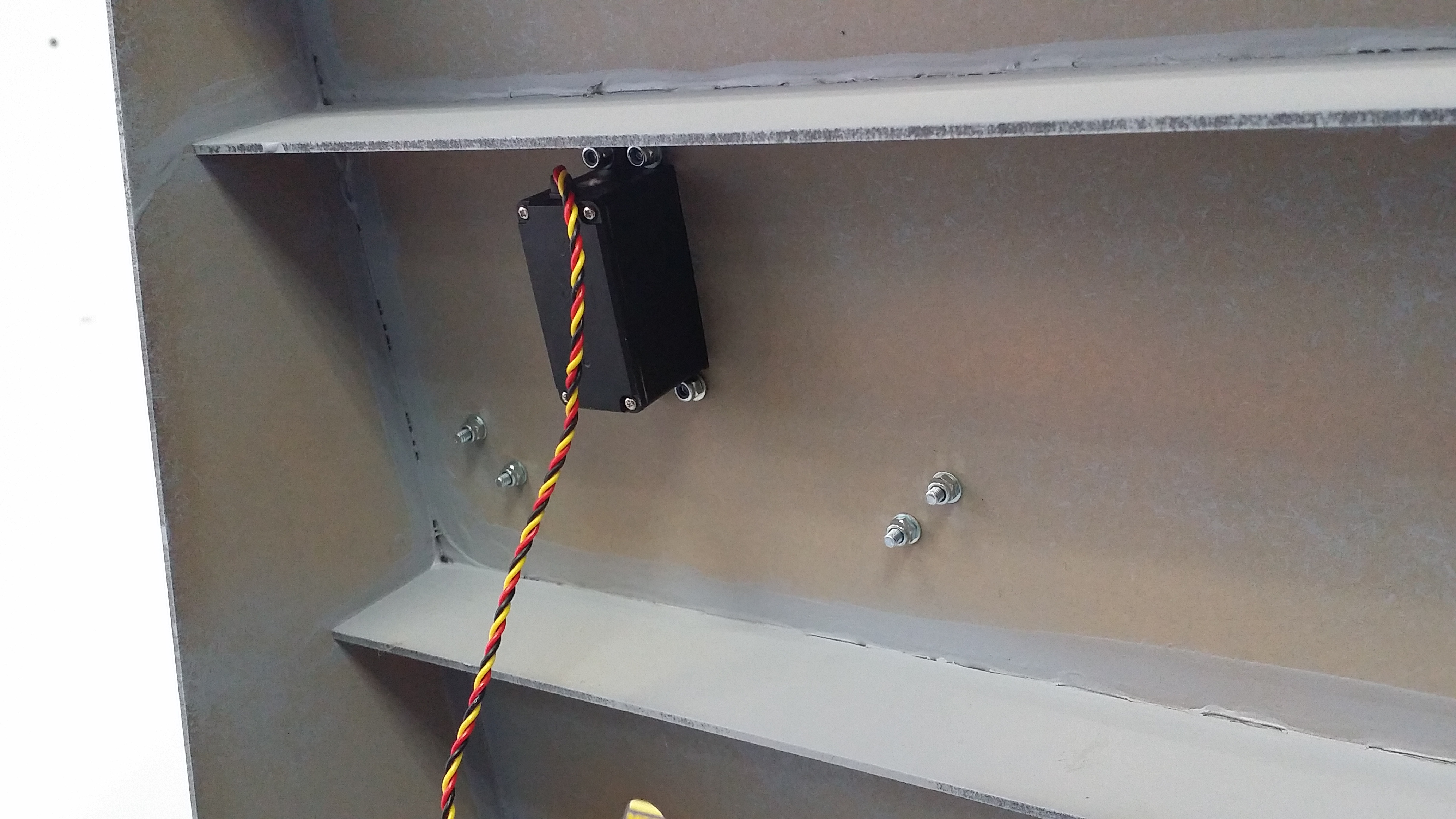
Here is the servo mounted. The roller mounts are also visible below.
Arm Hinges

I am using the potetiometer axles as hinges for the tension arms. The pots are mounted from the front. Wires go to the back. The idea is to keep the arms off the front plate and out of the way.
Back of Arms

Here are the arms visible from the back side. The pot axle will get another support bracket.
Tension Arm Slot

This is the arc that guides the tension arm.
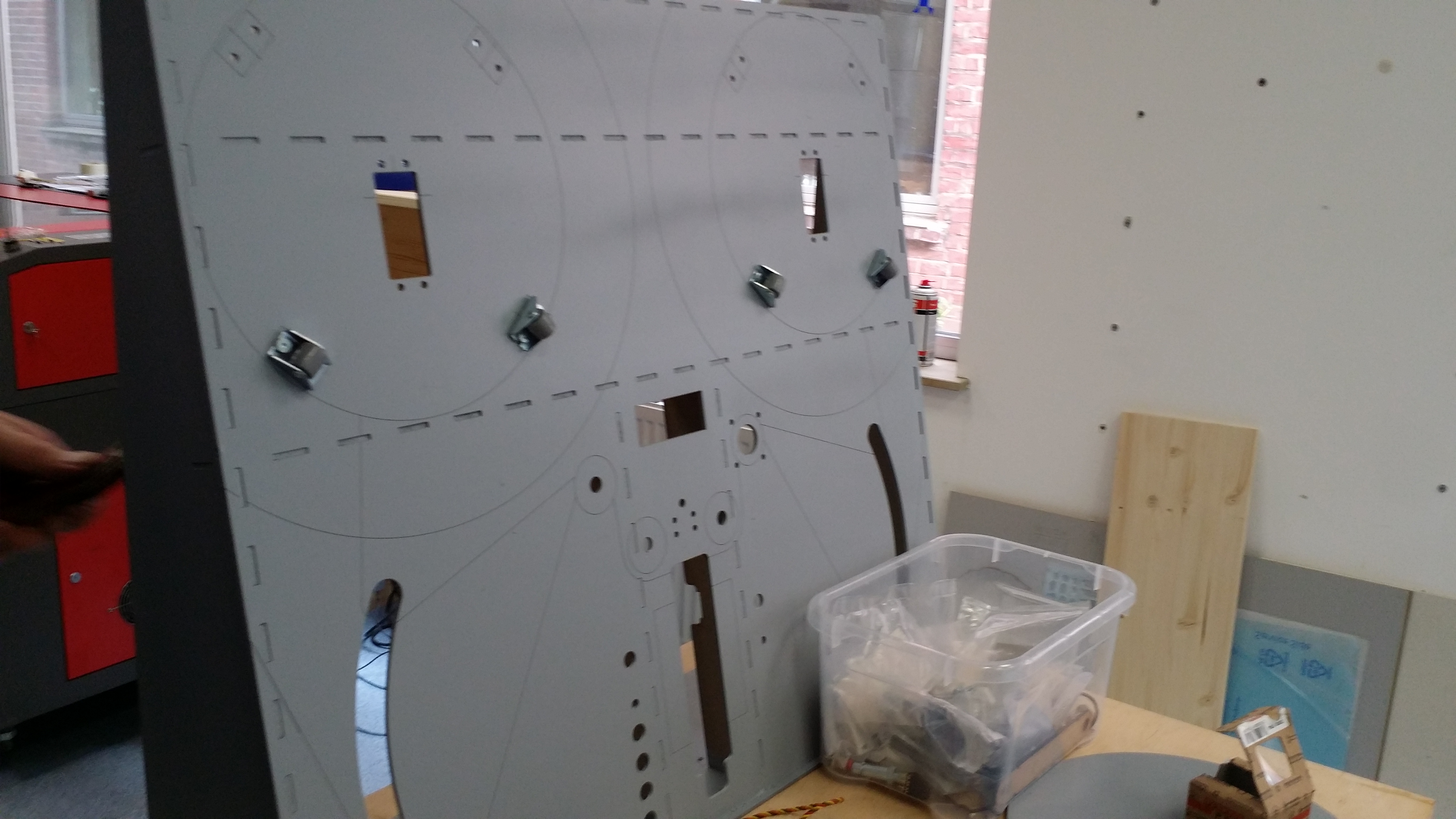
Mid-Build Overview
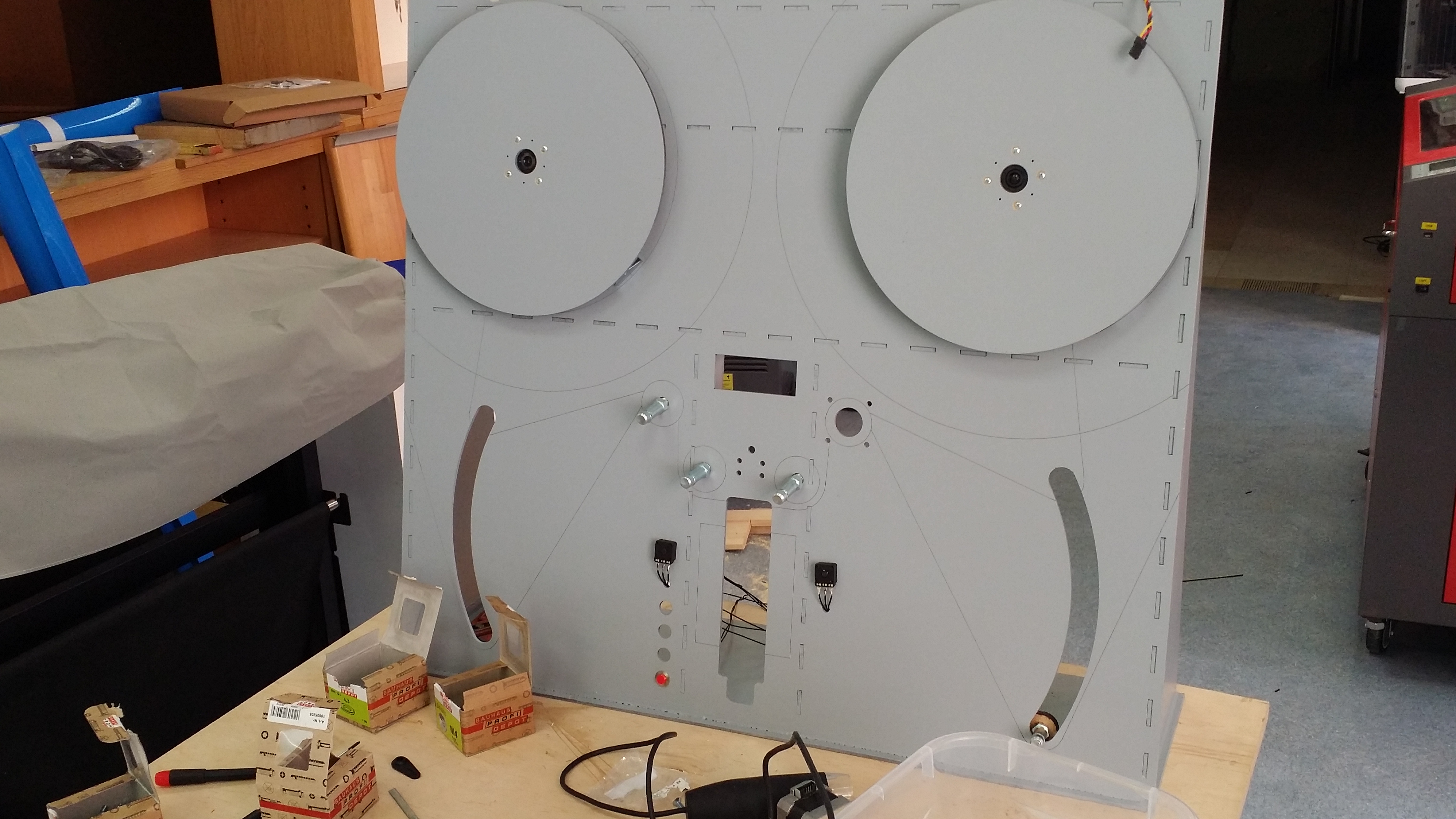
Here is the complete machine. Large reels would hang over the sides of the machine, but stay clear of any mechanics. One pushbutton is mounted at the bottom left. The bottom middle slot is for the microscope. The middle slot is for the 2×16 display (nothing fancy here at all). Three axles for the wheels are visible. The bigger hole is for the stepper.
Camera Mounts
Two metal profiles glued to the case will allow the camera to be mounted with magnets. Magnets make it easy to remove and adjust the camera.
Reel Hubs
Printed and mounted.
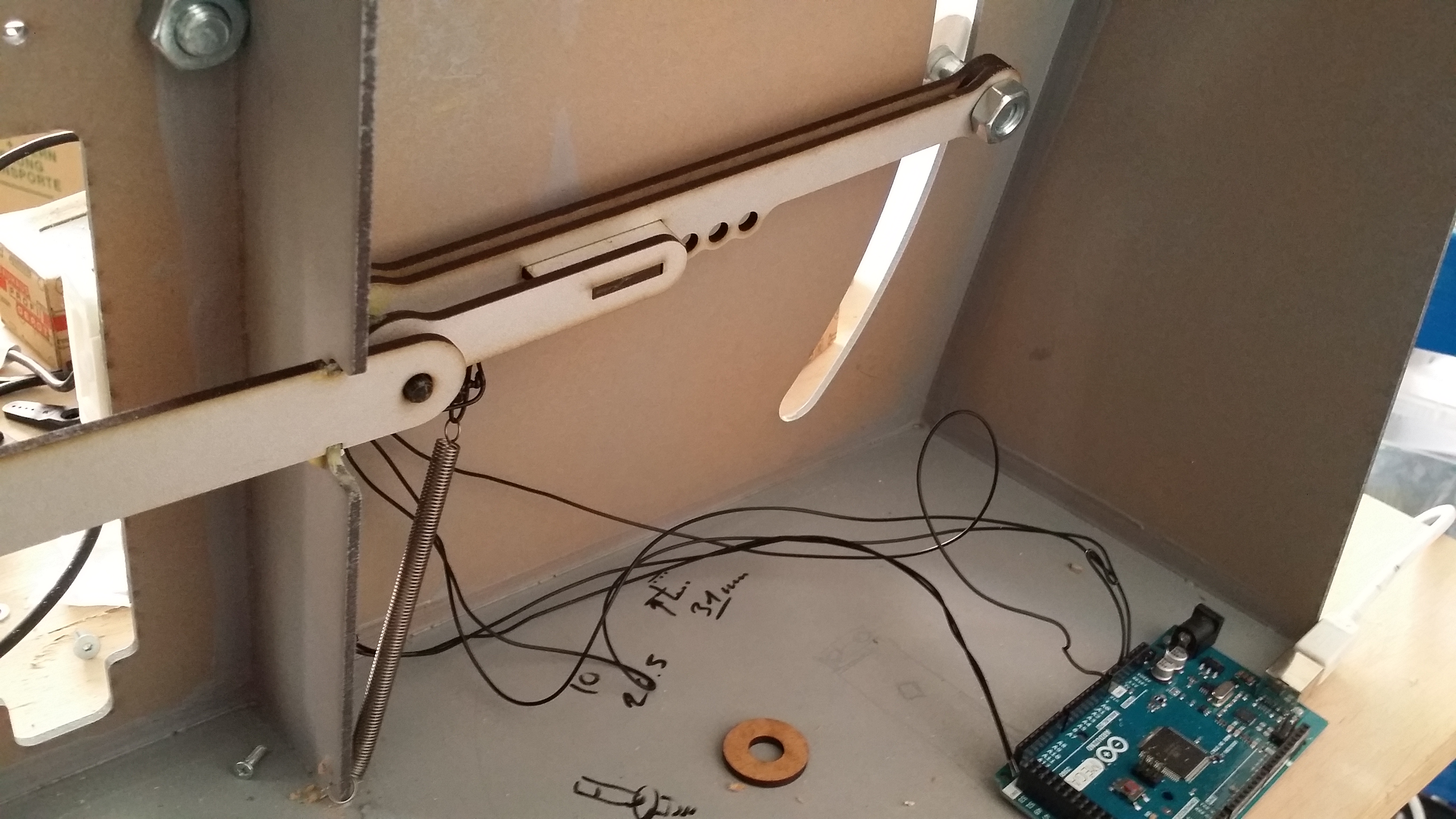
Arms with Roller Rods
Mounted all axles for all rollers. The numbers show the analog readout from the potentiometer when the arm is in the marked position.
Testing with Arduino

In a very simple test, the motor reacts to the position of the arm. This works reliably in keeping the arm level when film is move toward or away from the reel.
Printing the Rollers
I am printing the first roller that I designed in OpenSCAD. This takes 2 hours in best quality, so no testing until later this afternoon. The stepper motor is also in place, but needs a different hub on the transport wheel.
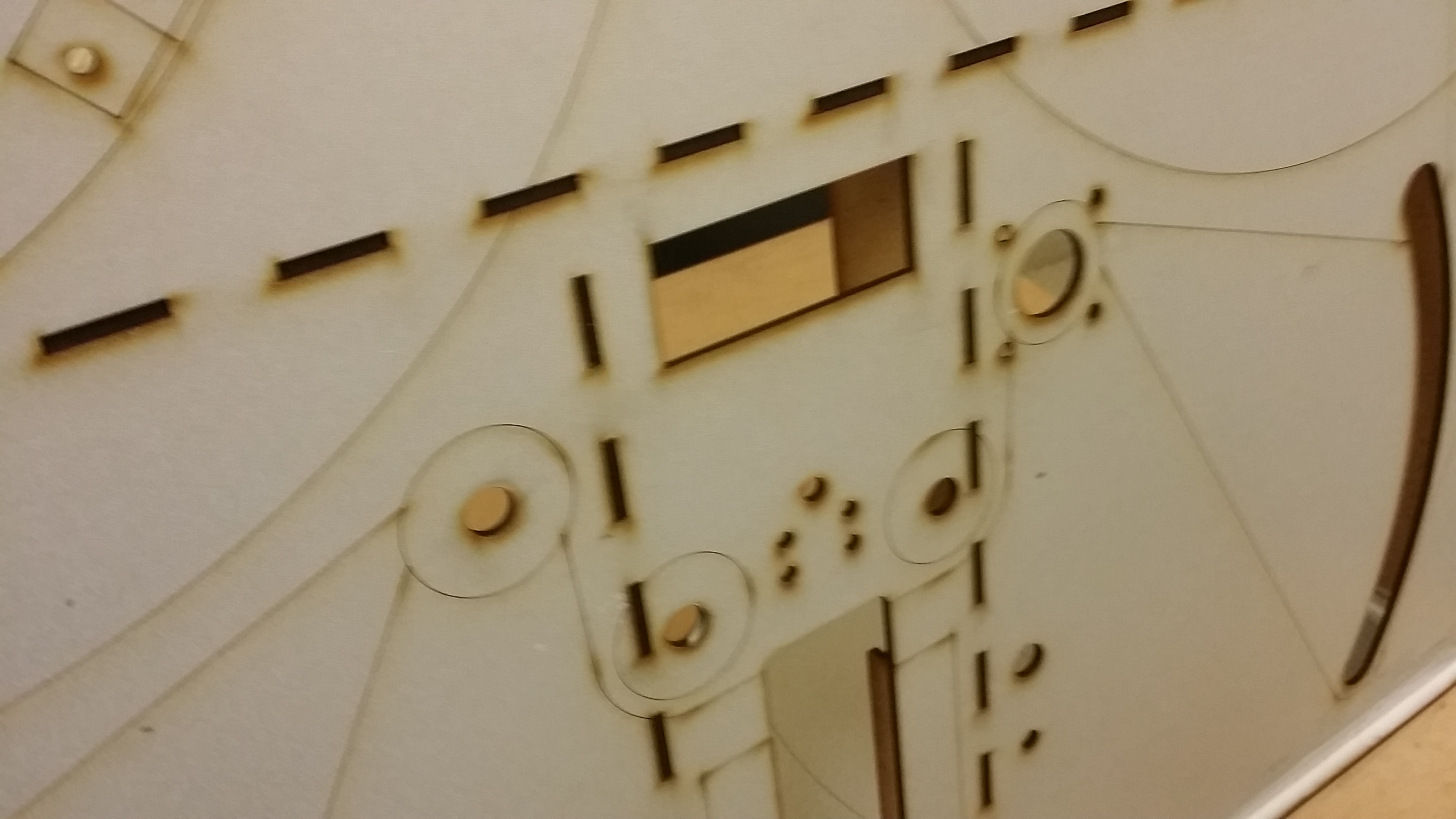
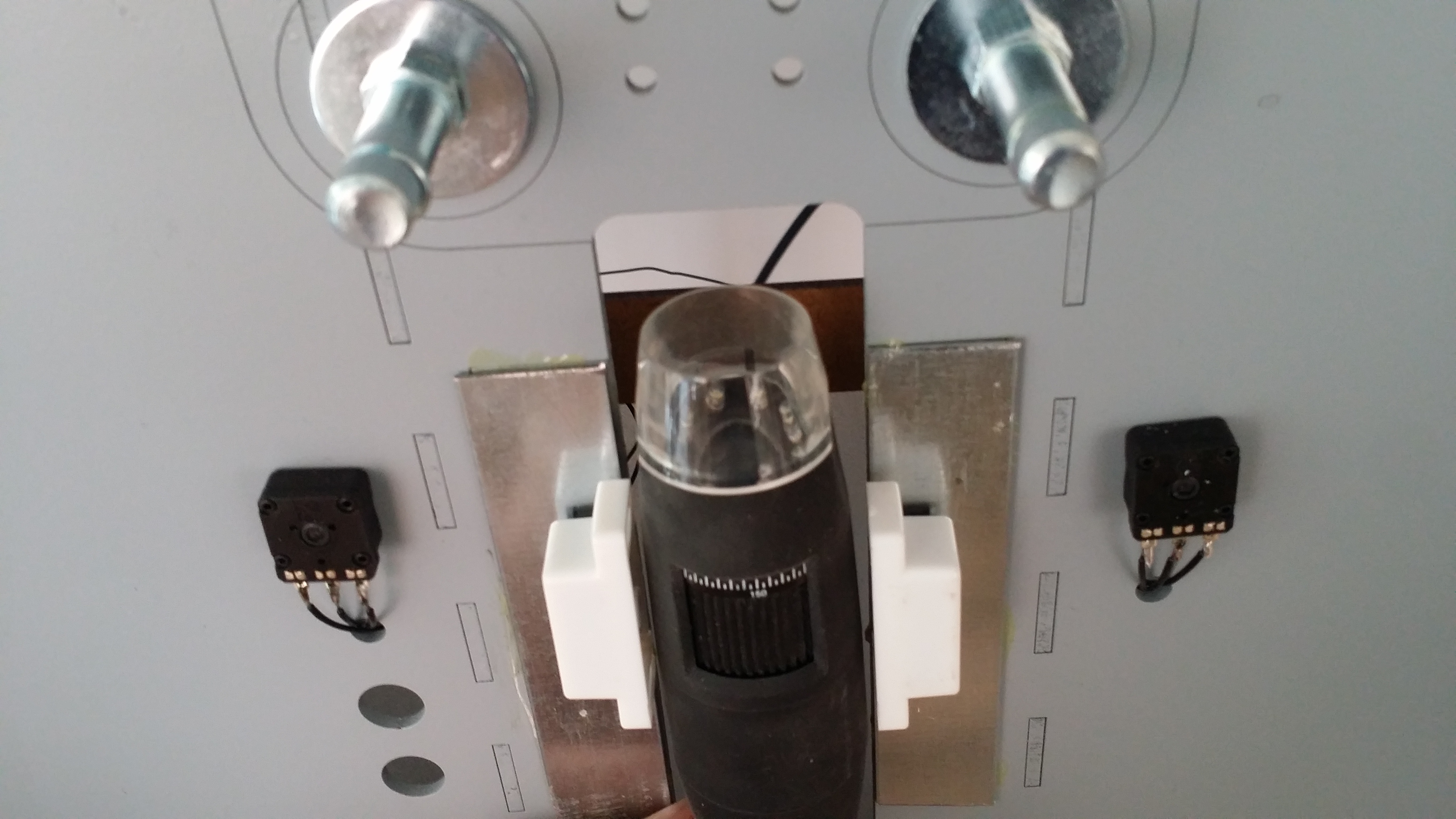
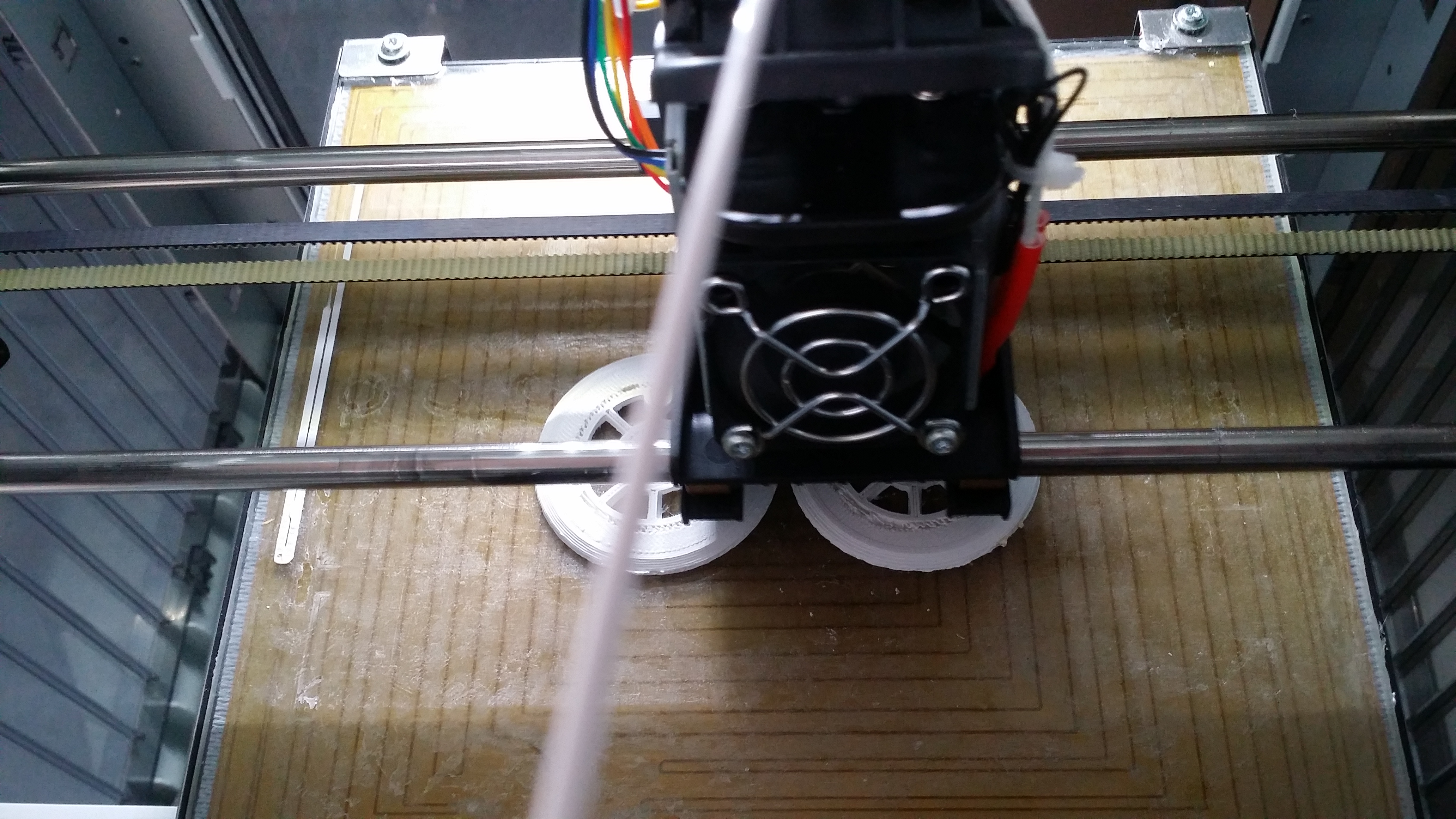
Transport Central

These rolls make sure that the film is flat and horizontal over the camera. The top right wheel is driven by a stepper motor for precise transport over the camera. At a first inspection, it seems that friction is too low to reliably transport the film strip. I will either have to make the roller turn more easily (use oil instead of grease), or connect two rollers with a chain (or all four), or add sprockets to the transport wheel. This would require another set of rollers. So glad that ABS extrusion is relatively cheap.
Tensioning the film

A closeup view of the tensioning roller…
… and the spring-loaded system that is supposed to pull the film down. The first (non-computerized) test worked. I will have to play with the spring tension a little to get optimum forces.
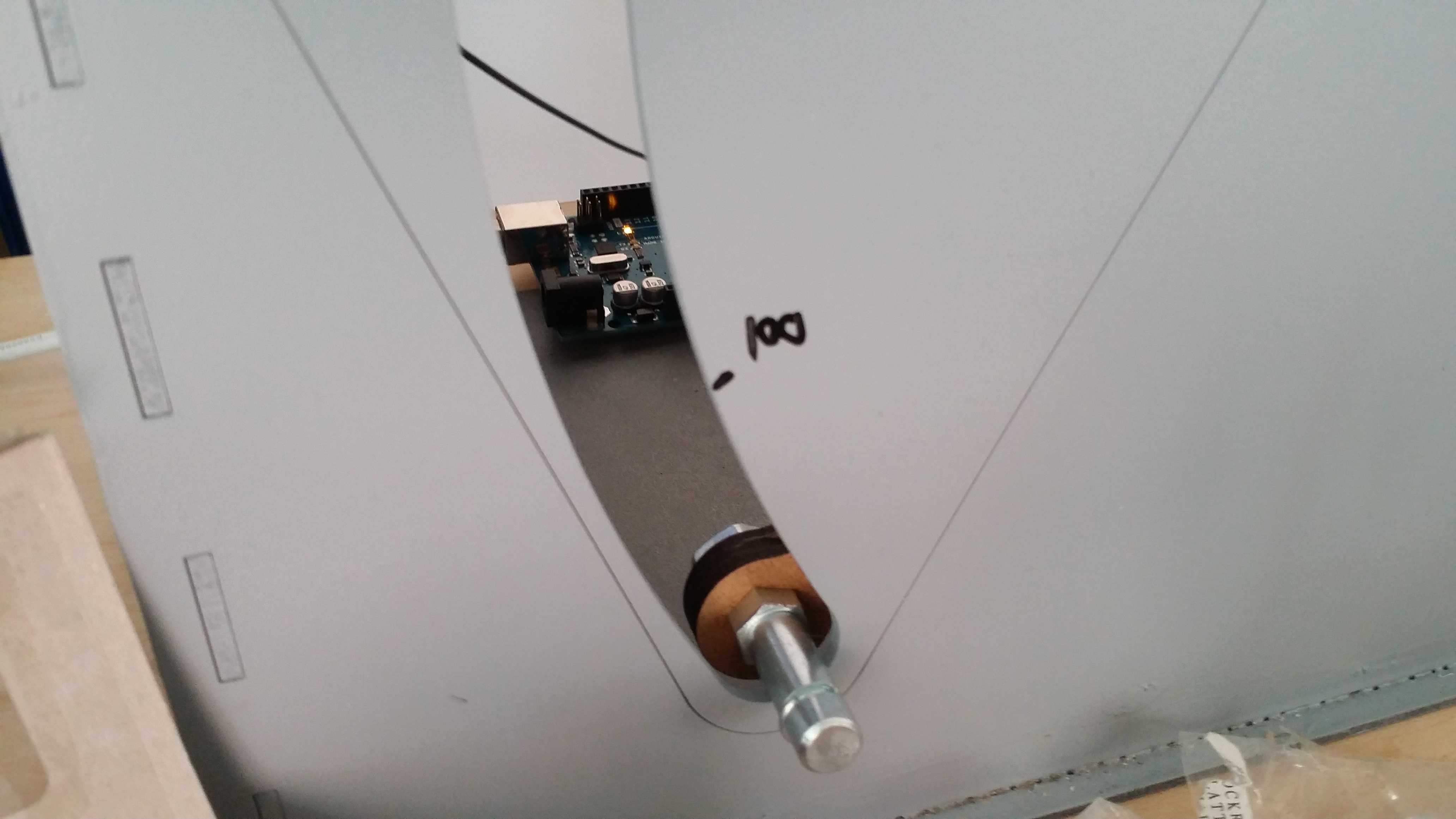
Film Loop
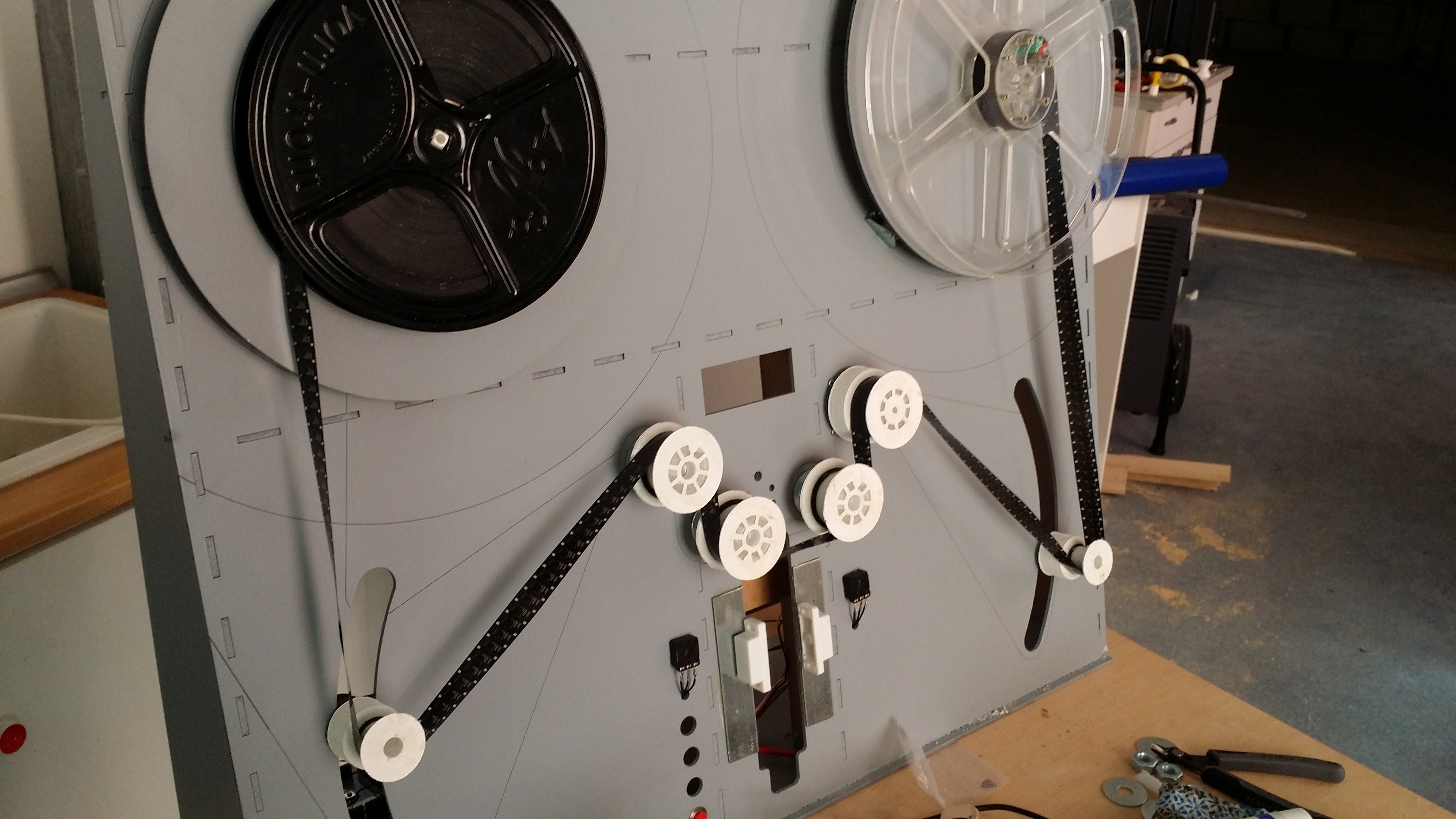
This is a view of the entire film loop. Maybe this clarifies what I was attempting in all the previous picture.
Magic Magnetic Microscope Mount
I am sure it is obvious by now: having access to a laser cutter is one fantastic help that can’t be understated.
Arduino hooked up
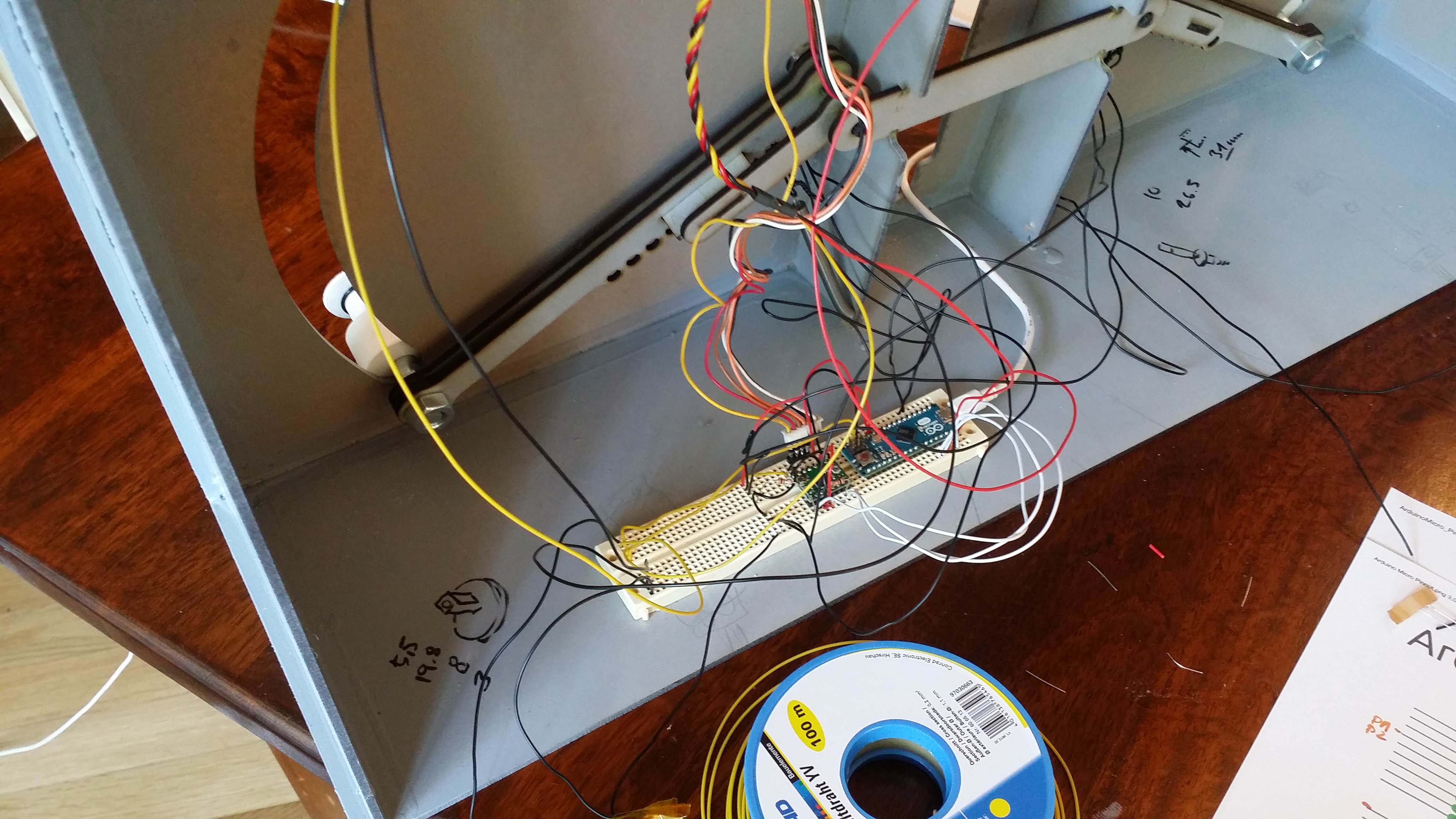
This is the Arduino Micro hooked up to the servos, the Polulo, and the pots. The Polulo is set to 16 microsteps to make operations as smooth as possible. Why doesn’t any of my screwdrivers fit on the tiny pot to adjust the current?
Find the wiring error and win some free beer.
Wire it up.
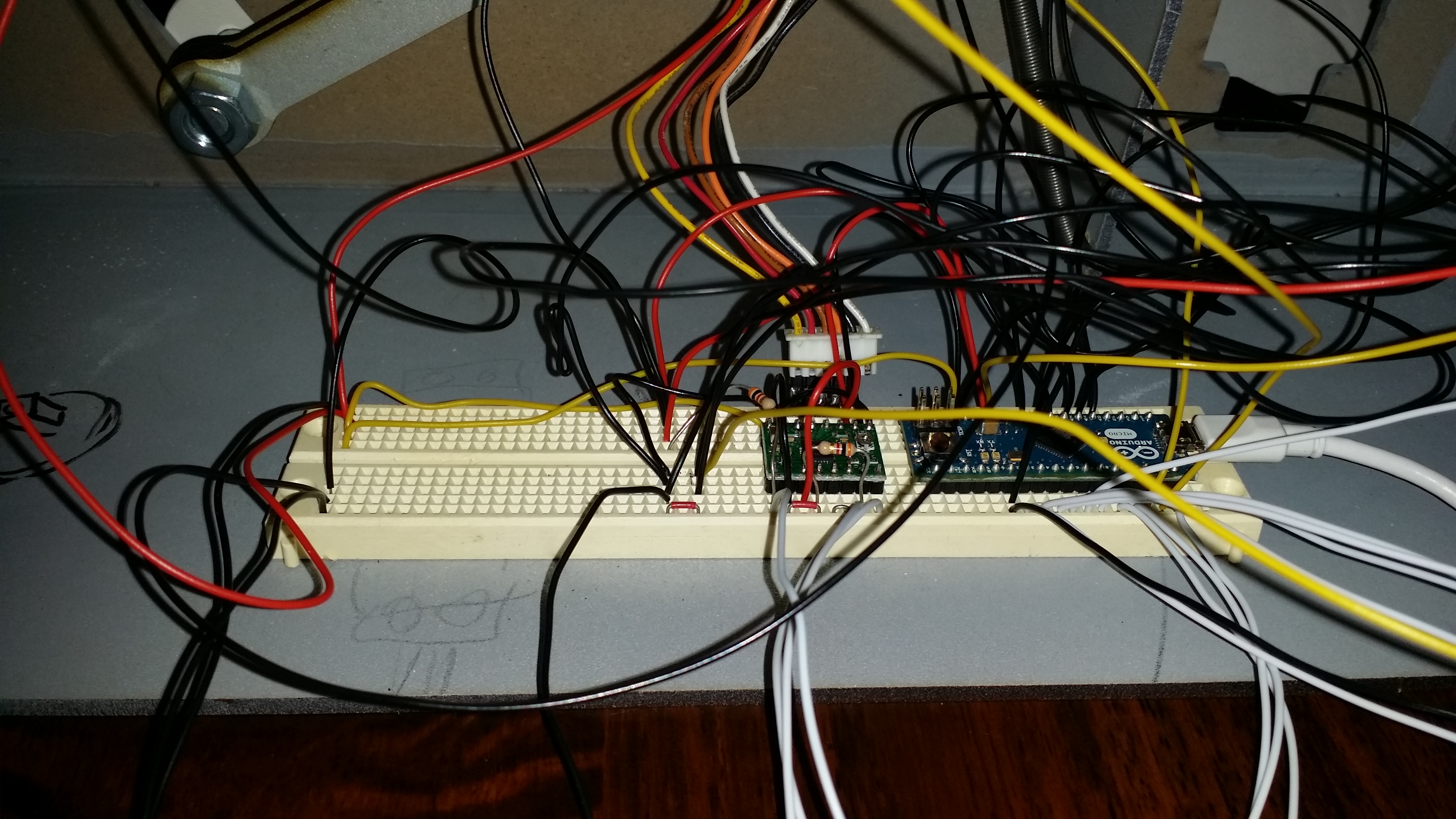
Some more confusing wiring. I added four buttons and an LCD display. 18 new wires.
And many of the wires are much too long. I forgot to make mounting holes to hold a harness. Maybe I will add that later.
Firmware 0.1
After calculating and poking around in the docs, I was able to write a tiny firmware that self-regulates the tensions and the feed via the arms. Very nice! The stepper cotrol needs more thinking. We need to ramp up and ramp down the speed and make the rotation as smooth as possible to make the transport as reliable as possible.
One button must disable the automatic tensioning, so that the reels stop spining when inserting the film. The scanner must reenable it softly without jerking the reels around. The reels should have a maximum acceleration coded into the firmware.
Host Software
Nothing yet. But I am happy to announce that my microscope works with OpenCV on OS X. I am very happy about that!
It’s time to create a little protocol between the machine and the PC. I need to be able to send relative positioning commands and receive a status report, so I know when the end of the film is reached or any other event happened.
Bold text items have priority.
| —- Host to Scanner | |
| m… | transport # steps forward or backward |
| s | sleep – all motors off |
| w | wake up |
| t… | set tension on arm 1 and 2 |
| v | request firmware version |
| ? | request to send status |
| q | quit – drive to safe positions, switch all motors off |
| r | rewind |
| f | fast forward |
| p | pause: cancel previous command and be alert |
| E | request for error message in text form |
| d… | print text on display |
| h | help (list all available commands) |
| —- Scanner to Host | |
| s… | status: arm positions, reel speeds |
| b… | user pressed a button |
| e… | error number |
| E… | error text |
| v… | send firmware version |
Also how about timeout commans, button assignments, menus for buttons and display?
Integrating OpenCV into an FLTK app to capture frames and find the index hole was very easy. Now I need to add code to send adjustment commands to the machine via serial port, read the machine status, and finally add the last grabbed picture to a movie file.
Easy as pie… .
A First Test!
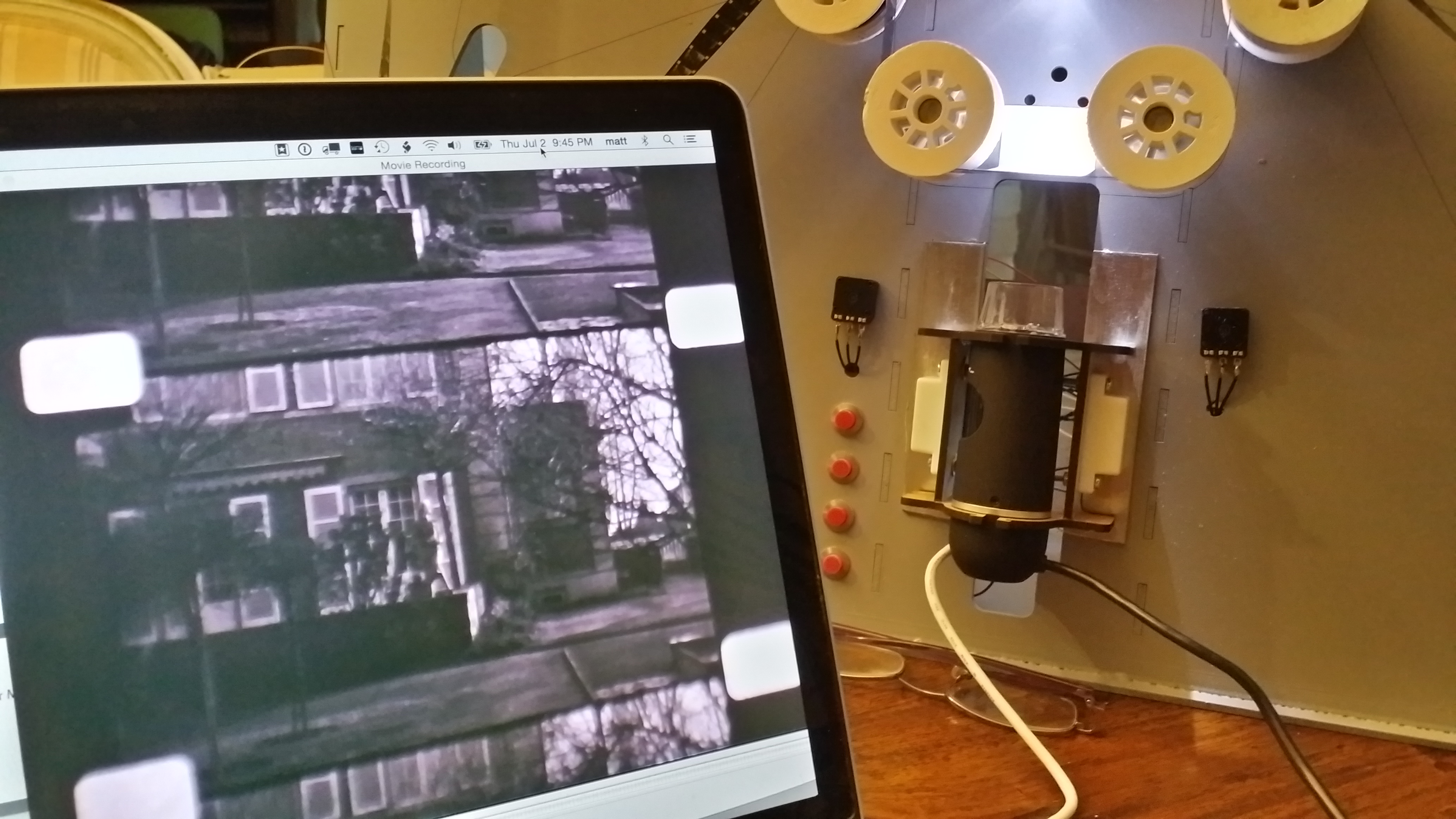
How exciting! I managed to read the first frame out of the machine. Focusing correctly is tricky. I may have to add a guide window to keep the film flat. Quality and resoluion however is amazing. And with a black base color film, finding those index holes is child’s play. Other film strips may be transparent around the index holes though, making registering a lot more sensitive.
Lighting the Scene
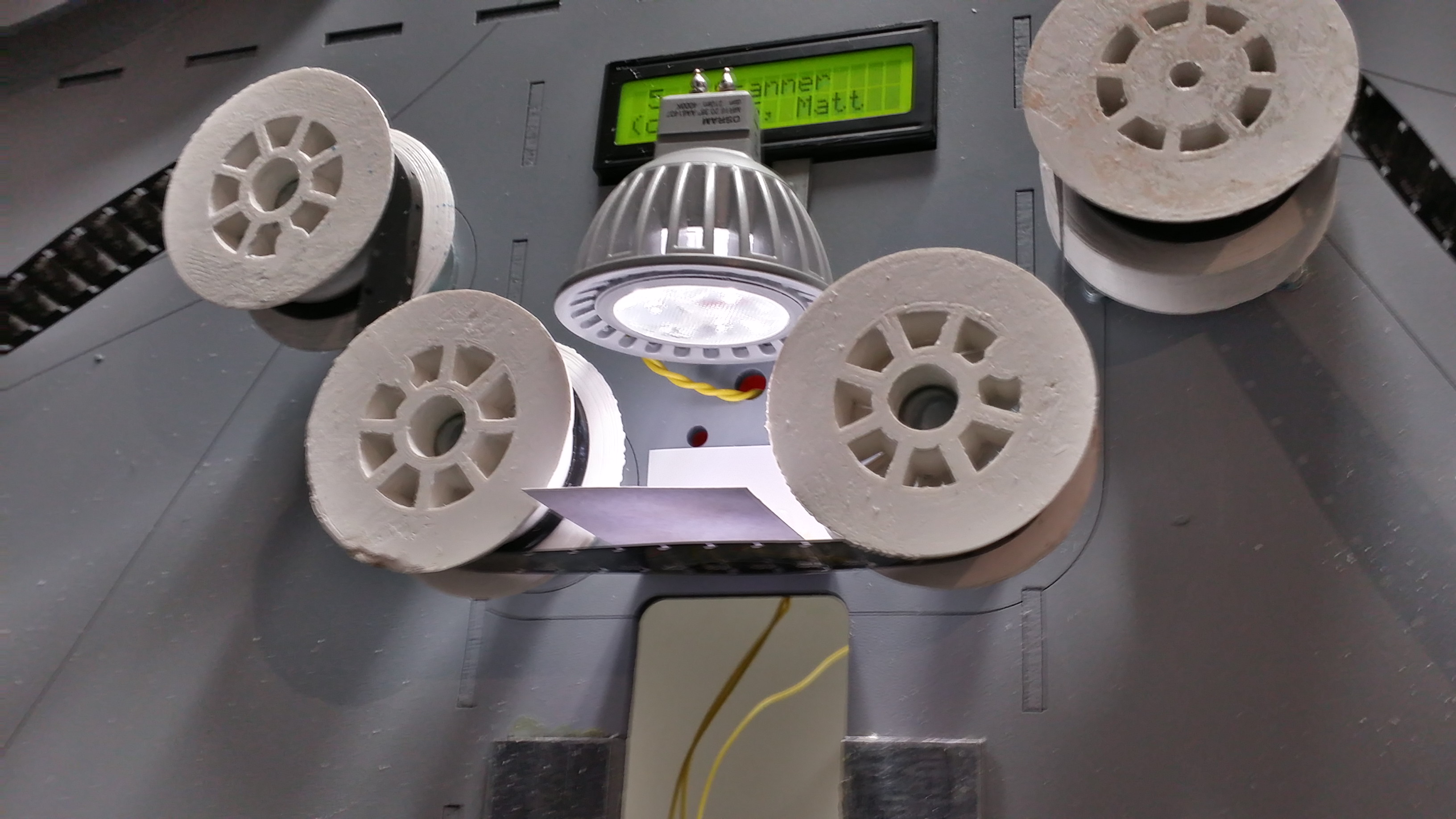
Dangling an LED torch from a wire is not the prefect lighting.
The new light source is a simple 12V LED bulb that I had laying around. This is good enough for B/W film, but may not be sufficient for color film. I am contemplating an RGB LED array to do color correction on the fly. But that is for version 2.0 or even 3.0.
A simple paper is used as a diffuser to spread the light more evenly. I will have to build a box, a film guide, and a better screen here.
I am using a simple transistor connected to one of the PWM outputs to control the LED light.
A First Movie Clip
And here wa have it. The very first clip of 2 seconds, semi-automatically scanned by my film scanner. There is obviously a lot of room for improvement. More importantly though, the initial concept works.
Room for improvment:
- transport precission: have a transport wheel with sprockets 3D printed
- roller precission: have rollers printed and add ball bearings
- color depth: the camera has an automatic gain control that we need to disable or distract somehow
- stabilization: beyond the mechanics, we need to find sprocket holes and use them to stabilize the image
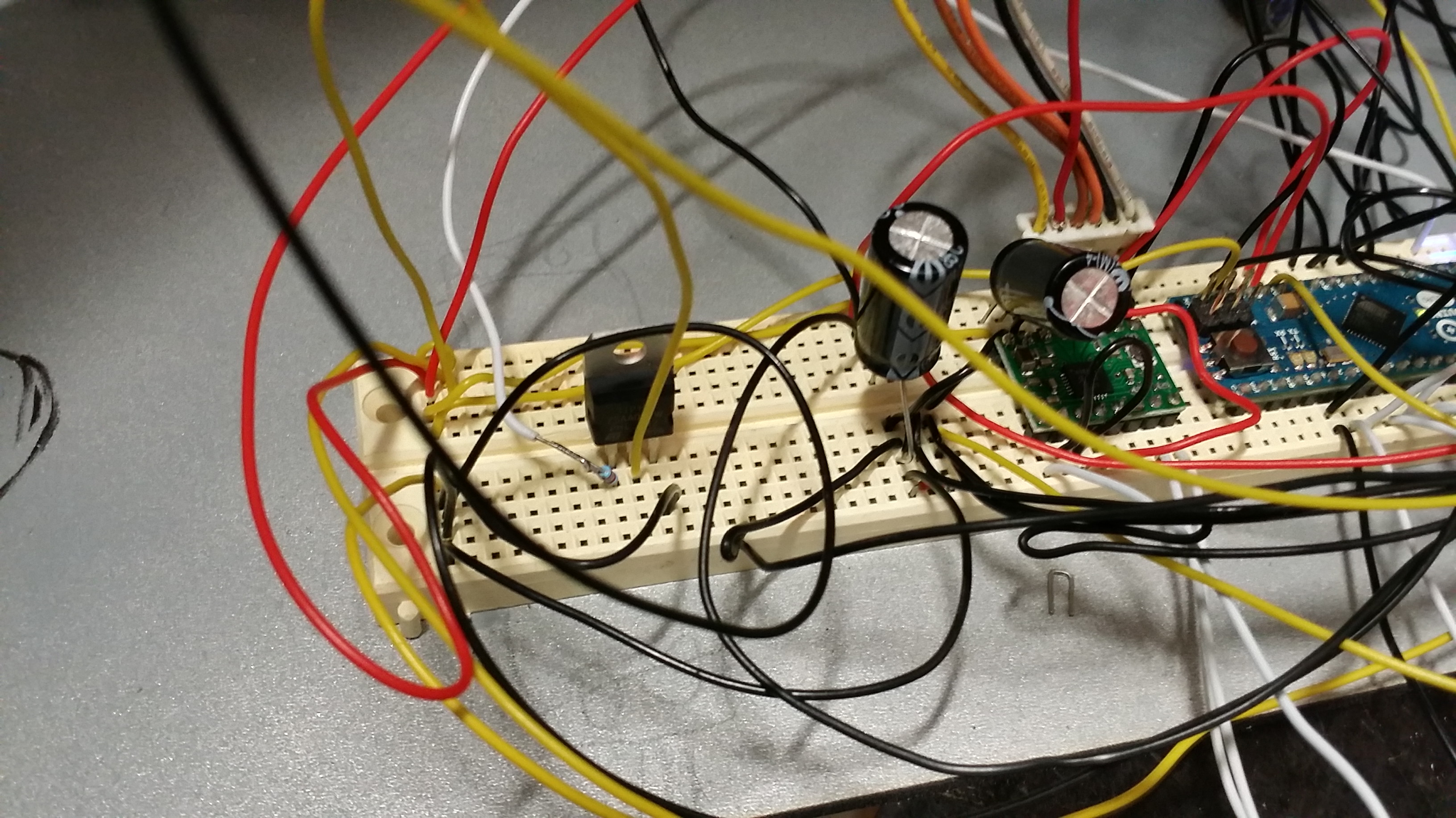
Power Distribution
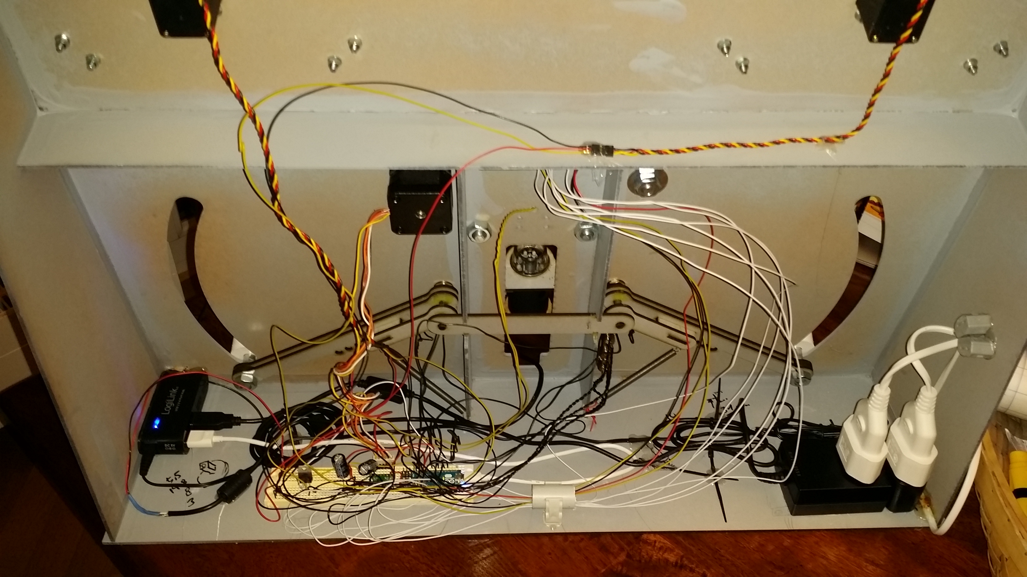
Yes, yes, it’s still chaotic in the back. I added a single power cord that runs a 3A/7.5V power supply for the motors and electronics, and a 5V supply for the USB Hub. The Hub connects the microscope and the Arduino to a single USB port and is working well. Wire management is still an issue.
Ball Bearings
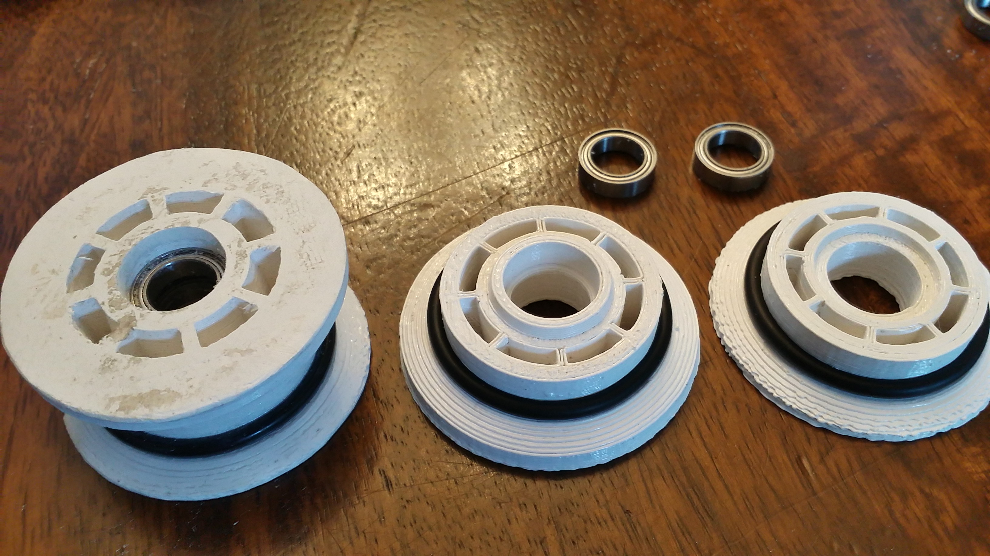
My first attempt at 3D printing rollers was far from perfect. To add prcission and reduce rolling resistance, I added ball bearings to the design of all rollers.
Pin Wheel Transport
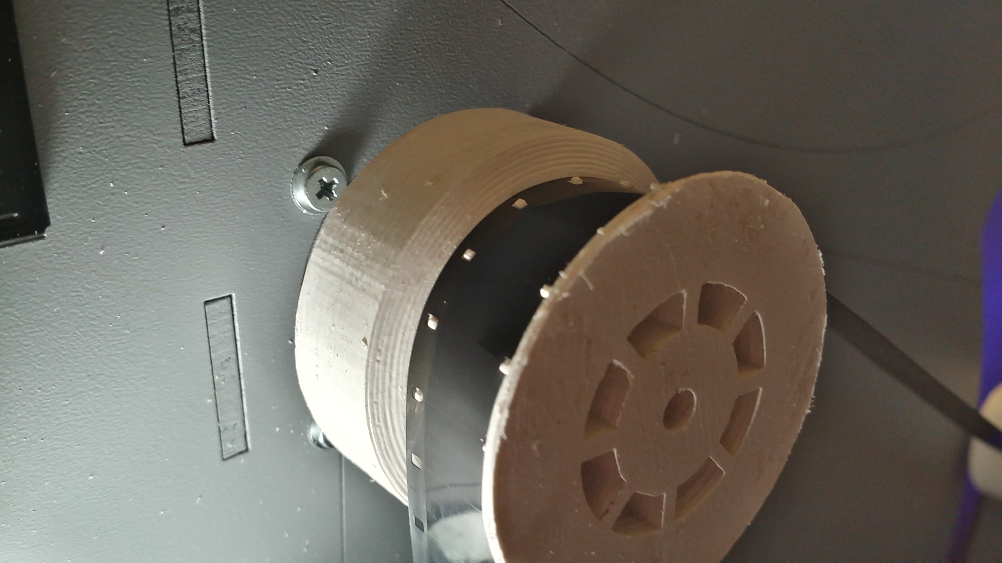
Transport was an issue from the beginning. I tried to get away with rubber rings, but there is always some slip and the film starts drifting. Using optical recognition to find index holes is nice, but quite involved. So I finally decided to print a transport wheel with sprockets. To my surprise, it works quite well and does not seem to damage the film. The sprocket distance should probably be corrected by 0.2 milimeter or so. ABS is always shrinking an a bit unpredictable.
A Second Clip
Here is a second clip. This one is scanned with the new pin wheel. The result was run through a stabilizer.
After scanning these two seconds, the film came apart where it was glued together. I ordered some old-school editing tools, but I will also have to update the software to put as little stress as possible on the film.
Incremental Improvements
I manged to improve the Arduino software today. It understands a few very basic commands over the serial port.
I also improved the host software by adding communication, and a record button that tells the Arduino to advance by one frame. With this simple setup, I was able to record a short clip automatically. Yay!
Here is a scan as it comes raw from the software. The image is pumping up and down which is an indication that either the transport wheel is not exactly round, or the rollers have too much play. Waiting desperately for the new 3D printer… .
And here is the same clip after stabilization:
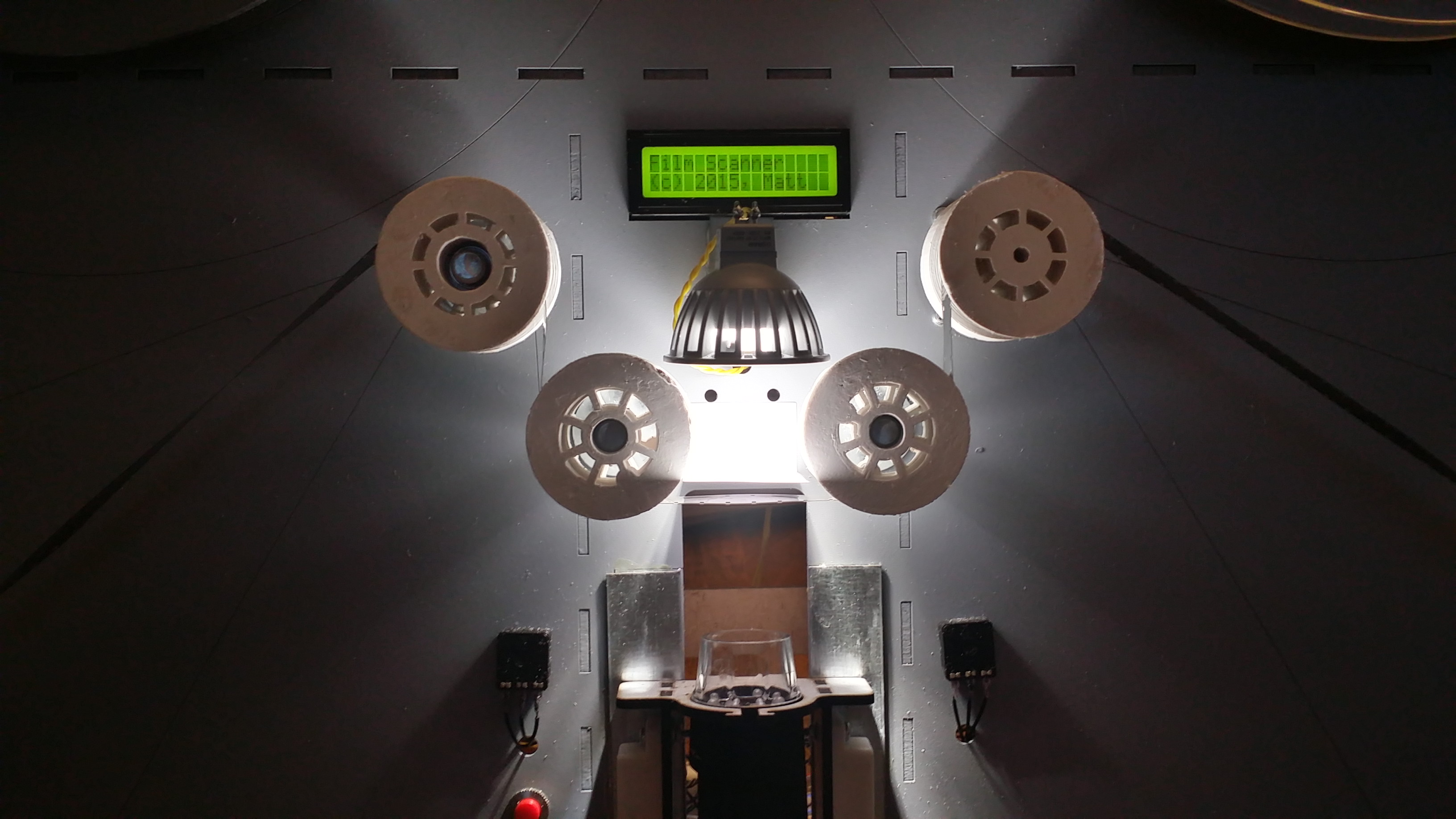
Here is the scanner at work. The firmware need a lot of improvement to keep the reel motors from twitching.
Remarks for Version 2.0
- Case
- make reel motor mounts slightly larger
- reel motor mounts need cutout for cable
- mounting holes along crossbars for wiring
- find better place for push buttons
- potentiometer cover
- Lamp casing and sunlight protection
- spring mounting holes below arm
- shorter arms, less torsion, less space
- Microscope cutout not needed? (even for 8mm?)
- Alternativey, all components closer to case
- PCB Mount, Power supply mount, USB Hub Mount
- Felt Guide for film window
- Transport Handle at the top
- V3.0: add table for glueing film, little pocket for white gloves and for glue (glove compartments)
- close case on the back side!
- on/off switch in power line
- Electronics
- RGB LED’s with PWM control for every component?
- make PCB and wire harness
- lighter and clicking buttons
- Microscope
- holder: adjustable height
- automatic focus, manual gain control (B/W possible if we use RGB LEDs!)
- better diffuser (white acrylic? sand blasted?)
- Rollers
- CNC machined on Lathe for improved quality
- Firmware
- fast rewind via reel1, arm1, roller, reel2
- avoid high tension
- avoid oscillating, but also avoid continuous power to the servos
- protect motors when digitasation interrupted
- detect end of film
- Software
- UI concept, simple controls
- zoom for easier manual focus (give quality indicator)
- image stabilization, find index holes, color adjustment, …
- try to create HDR with multiple exposure, map to 8 bit with curve
- Documentation and Publication
- DXF files for case
- OpenSCAD and STL files for rollers
- parts list
- wiring diagram
- source code for host and machine
With a laser cutter in reach and less than 10 Euros of wood required to build the case, I am quite seriously thinking about building a new case for the machine. The current wiring is horrible, and transporting the machine is pretty much out of the question. Reliability is quite important, because the scanner will sometimes have to run unattended for several hours.