
Building the Pwdr 3D Printer
Introduction
3D printing is here to stay. After 20 years or so of a life in the shadows, 3D printing has gotten a lot of press in 2012, triggered by the OpenSource FDM printer “RepRap Mendel“, and then turned into a blaze by Bre Pettis and his “CupCake“. These printers have brought prices down from 60.000 and more Euros to under 500 Euros by providing OpenSource software and hardware kits.
FDM – Fused Deposition Modeling can be understood by imagening a Hot Glue Gun bolted onto a CNC machine. The parts are built from ABS or PLA and have typically a ribbed surface from layering the lines of hot plastic.
But FDM has its limitations. There are many more 3D printing methods out there. One of them uses ink jet print heads to fuse layers of plaster. This method is pretty old and commonly refered to as “Powder bed Printers”, or PP. These systems are great for arbitrary shapes as the loose powder supports the hardening parts of the model. Also, powder printers can be made to print 3d models in full color.
So, while there are probably hundreds of OpenSource FDM Printers out there, nobody seems to have published a powder printer. Until summer of 2012.
Pwdr, a great approach to powder printing
Alex Budding designed and built Pwdr as part of his graduation project at the University of Twente in the Netherlands. He published his plans in a very clean way under Creative Commons, which means that we can build our own versions of his printer.
And that’s what I am going to do.
Building my own Pwdr
There are two main reasons to build this. First, I want to show my kids (7 and 9) that it is possible to build great things pretty much from scratch. They are interested in programming and elektronics, and they also know how to create 3D models on the computer. A 3D printer seems like the perfect project.
Well, and admittedly, I always wanted one of these mysellf. 😉
Getting the materials
Alex has put a great BOM online. I am in the process of sourcing all parts locally to avoid taxes and customs. This is ho far I got:
| # | Description | Status | Comment |
| Mechanics | |||
| 4 | Acrylic GS 790×384 8mm | OK | hardware store (1) |
| 1 | Acrylic GS 384×384 5mm | OK | hardware store (1) |
| 10 | Timing pulley GT2 d=9.6mm 6mm | OK | www.maedler.de (2) |
| 3 | GT2 Timing belt 560mm | OK | www.maedler.de (2) |
| 1 | GT2 Timing belt 112.00mm | OK | www.maedler.de (2) |
| 1 | GT2 Timing belt 130.00mm | OK | www.maedler.de (2) |
| 6 | Ball bearing d=8mm 2mm | OK | www.maedler.de |
| 1 | Precision Shaft d=4mm 260mm | OK | www.maedler.de |
| 2 | Precision Shaft d=6mm 220mm | OK | www.maedler.de |
| 1 | Precision Shaft d=10mm 210mm | OK | hardware store |
| 3 | Precision Shaft d=4mm 25mm | OK | www.maedler.de |
| 2 | Precision Shaft d=8mm 500mm | OK | www.maedler.de |
| 4 | Sleeve bearing d=12.70mm 4mm | OK | www.maedler.de |
| 4 | Sleeve bearing d=15.90mm 8mm | OK | www.maedler.de |
| 6 | Sleeve bearing d=12.70mm 6mm | OK | www.maedler.de |
| 100 | Fastenings M3*12 | OK | hardware store |
| 100 | Fastenings M4*12 | OK | hardware store |
| 100 | Square nut M3 | OK | hardware store |
| 100 | Square nut M4 | OK | hardware store |
| 2 | Linear position drive LS41 | OK | http://de.nanotec.com |
| 2 | Lead screw nut | OK | http://de.nanotec.com |
| 3 | Nanotec Stepper Size 42 | OK | http://de.nanotec.com |
| Electronics | |||
| 1 | Arduino Mega 2560 A000047 | OK | www.farnell.de |
| 1 | Arduino Mega Proto Shield A000038 | OK | www.farnell.de |
| 1 | 0.1uf Capacitor | OK | www.farnell.de |
| 1 | 1.0uf Capacitor | OK | www.farnell.de |
| 1 | 240 ohm Resistor | OK | www.farnell.de |
| 1 | 4K0 ohm Resistor | OK | www.farnell.de |
| 2 | Darlington Array ULN2003 | OK | www.farnell.de |
| 1 | Linear voltage regulator LM317T | OK | www.farnell.de |
| 1 | Socket FCC Molex | OK | www.farnell.de |
| 2 | BigEasy Driver | OK | https://www.sparkfun.com |
| 3 | EasyDriver Stepper Motor Driver | OK | https://www.sparkfun.com |
| 5 | Pololu A4988 | OK | alternative drivers from http://www.watterott.com |
| 1 | HP Black Cartridge C6602A | OK | www.sullvan.de |
| 1 | HP Cartridge Assembly | OK | www.sullvan.de |
| 1 | Power supply 24V | OK | www.farnell.de |
| 1 | ATX power supply 1500W 15A | OK | www.farnell.de |
| Optional Parts | |||
| 1 | LCD Display 2×16 | OK | https://www.sparkfun.com |
| 8 | Pushbuttons | OK | www.farnell.de |
| 4 | End Stops (photoelectric fork sensor) | OK | www.farnell.de |
(1) – I decided to use wood instead of acryllic to keep cost down
(2) – using T2.5 teeth is much cheaper than the original GT2 version
Useful Links
- Pwdr Home Page on GitHub
- Download Files and Plans
- Discuss Issues
- Wired Article on the potential of this machine
Operation ??? Monkey
Do you have any suggestions for a powder/liquid mix? Send it to me and I will try to get the materials and do a test print
Operation Muscle Monkey
No tests yet, but I bought some Benefibre/sugar mix at the local gym. Five spoons full go into a glass of water if you want muscle. As a prototypical geek, I do not need muscle, and so this will go into starch (potato starch for now, because corn starch is harder to get in Germany). I will hopefully get a test going tomorrow – time permitting.
Operation Japanese Monkey
Ah, a new mixture. Dental plaster plus rice wine! So far, the results look somewhat promising. One of the sample blocks has much less bleeding than the rest. I wonder if the model will hold up (but I need to be patient for another hour).
Operation Inked Monkey
Interesting! I let the Gin cartridge in the printer over night and it emptied completely into the plaster, leaving an unsightly blob of Juniper juice and dentistry devices. It seems the alcohol has destroyed the nozzles and found its way out through some broken seals. Bye, Gin cartridge.
Now, I only had the black in head left, so I tried it on the dental plaster. The result is the same crumbly mass that I observed using other powders with ink. Ink is not an optin (and neither is Gin for these HP cartridges)
Operation Yellow Monkey
After the calculation below, I figured I need plaster that requires less water to solidify. I tried dental plaster (ultra hard, 1:5 Water to plaster, yellow) with my Gin cartridge.
Result: I managed to solidify the plaster and get some shape! Even though this looks not much like the monkey, I did generate the rough shape. So what went wrong? For making tooth imprints, the plaster needs to be evenly mixed with the water within 20 seconds. To make that easier for a plaster that needs so little water, the manufacturer add flow enhancers. Great news for dentists, bed news for us: the flow enhancers make the plaster bleed to all sides like crazy (many millimeters!), ruining our shapes.
Nevertheless, Yellow Monkey is a great success, proving that the concept is good and the printer actually works.
Operation Drunken Monkey
I bougt some medelling plaster at the store and loaded the cartridge with Gin (Vodka is recommended, but I only had Gin – sorry). While the Gin was probably just fine, the plaster was horrible. It required litres of water, and the packaging clearly announced 24 hours dry time. Doh.
Result: let’s not talk about it… .
Operation Black Monkey
I did a few tests on paper until I was sure that everything is fine. Then I loaded the machine with plaster (only to find out that I bought the worst plaster ever with up to penny-size rock-hard pieces in it) and sliced the Blender Monkey into 10x10x8mm. The file was copied onto an SD card and printed through the Arduino firmware.
The final model was too weak. This is probably due to multiple factors. The plaster was bad, the ink saturation was too low, ink itself is a bad idea (Vodka is better), and of course I lacked the patience by digging the model out after an hour instead of waiting until tomorrow.
Result: the monkey head was there and had a blob shape, but then crubled into a million wet pices. Ooops.
Apr 21st 2013: Math Time
After another failed attempt (Alcohol and plaster of Paris), I guess I have to do some math again.
- 1 drop of in is 160pl (pico Liter) covering a 0.25 cubic mm voxel
- so, 1l = 1dm^3, 0.25mm = 0.0025dm, = 1,5625e-8 l
- pico is short for 10e-12, so 160pl = 160e-12l = 0,0106e-8l
- 1 voxel of plaster is1.563 / 0.01 = 156 times the amount of the ink drop
- this particular plaster is mixed 1 parts of water to 2 parts of plaster (by volume)
- so to have the correct ratio, we need 156/2 = 78 drops per voxel (0.25mm layers) or 31 drops on 0.1mm layes
- super hard dental plaster mixes at 100:20, so we “only” need 32 drops per voxel / 12 drops on 0.1mm
Phew. Now, I did test 60 drops without success, meaning I am still doing something wrong.
Observations:
- the plaster sucked!
- everything gets really dusty, everything
- the roller has a slight wobble which is disasterous for the model quality
- the x transport is really great now, quiet and reliable
- after much alignment, the y axis is now fine as well
- the z pistons never caused a problem, easy
- the amount of powder picked up is the same as the amount layed down, so there is close to ne spill!
- I will have to experiment with the powder/ink ratio a lot, test patterns are needed
- the plaster really sucked, in case I did not mention that before
- and yes, the machine is slow, but so was the original CupCake, and look how far those machines got
Task list:
- get a precise roller
- get better plaster
- generate test patterns for the ink/powder ration and layer height
- make the host software user friendly
- optimize
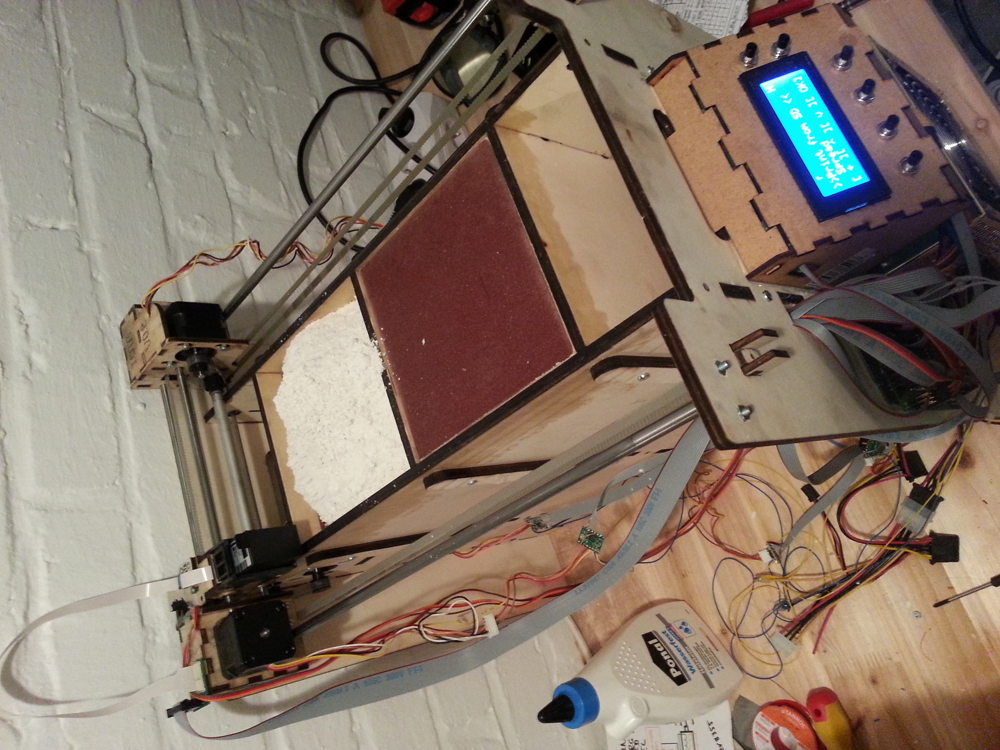
Powder goes in Z1, the feeder hopper in the back
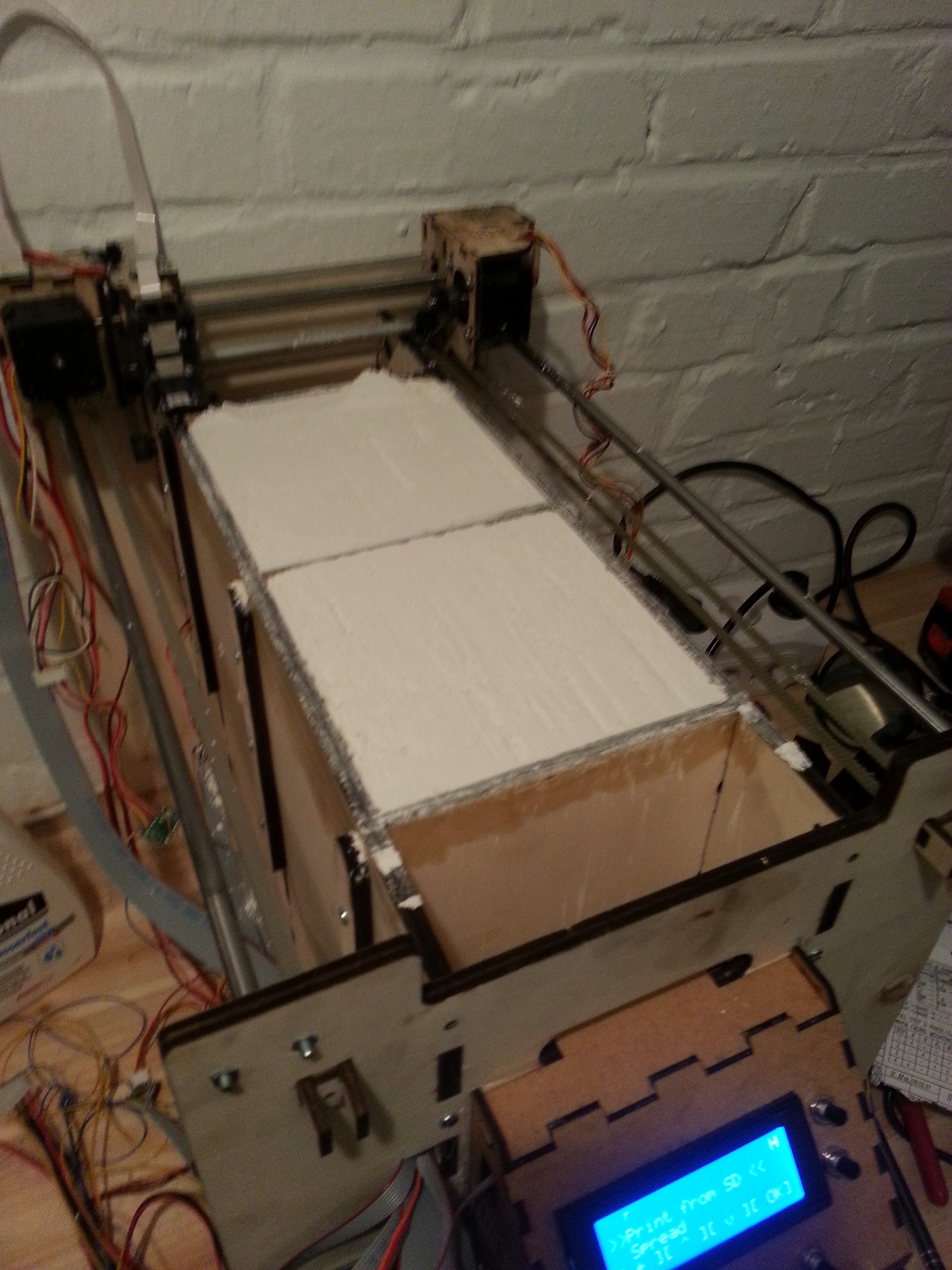
And is then transported and spread into the front hopper, Z2.
The printing process:
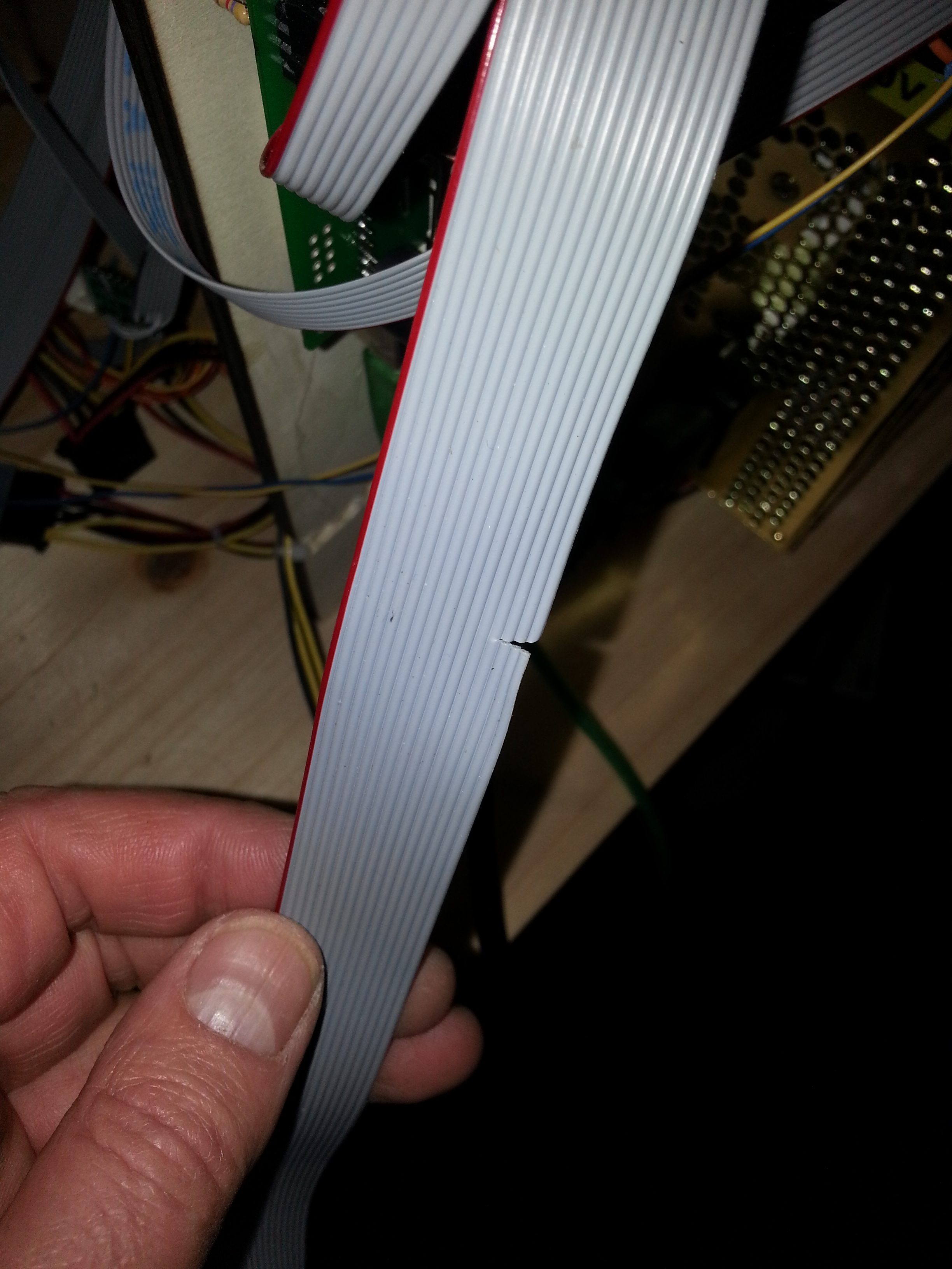
So I thought that a nozzle on my first print head died. AFter exchanging the head, the same nozzle did not work – huh? After checking the carrier, the chips, the connectors, I finally found the culprit: a hectic cut while soldering close to already wired connections. See the picture on the left.
Apr 17th 2013: This is my Interpretation
I just finished the essential commands for the 3dp file reader and interpreter.
All the slicing work, compilation, and optimization is done in the PC software where most of the computing power is available. Printing data is then stored in a proprietary .3dp file format on an SD card. The Arduino interpretes this file and sends the commands to the hardware interfaces. No PC is needed during printout.
Slicing and writing the .3dp file is next.
TODO: the ink cartridge needs a cleaning and capping mechanism
Apr 16th 2013: Hooking it Up
Today was the day when all the hardware came together. All motors are moving, all end stops are signaling, all buttons are working, and all pixels light up. The firmware grew, and I can run tests on all those functions. Now the art will be to control the motors in the order required to generate a 3D model… .
Apr 15th 2013: Menus and Buttons
I replaced the push buttons on the panel, and hey, everything is working just fine. So I proceeded to recreate the firmware from the code samples I wrote over the last weeks, giving me an About Screen and a tree-style Menu Structure. Now I have a 90’s telephone style menu to access test routines and whatever else I need to set up the machine.
Apr 14th 2013: Mounting the Panel
I had a few minutes today to mount the control panel and test the i2c command set, only to find out that the buttons I ordered were closed contact, opening when pushed. That won’t work in a matrix, so I’ll have to replace the buttons tomorrow. Luckily, I can get them locally.
I did fix many issues in the laser software, hoping that I will be able to cut complex parts again soon.
Oh, and while sourcing, I found spring-loaded contacts that are relatively cheap and will make for a great connector for the HP 45 cartridges (or whatever other cartridge comes my way).
If anyone has more information on the Xarr 128 cartridges, please contact me. Thanks!
Apr 13th 2013: The Control Panel
I lost the dongle to my laser cutter software. It took my three days to get that thing back up running again, and it is still not working all the way. At least, I managed to cut out parts for the control panel.
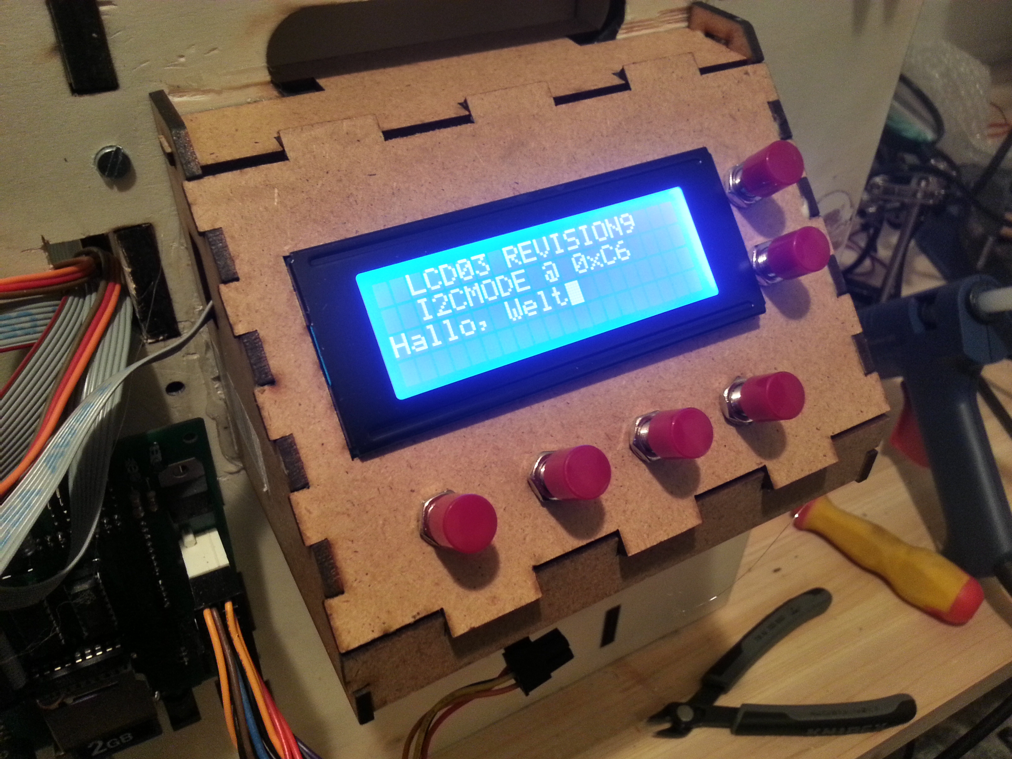
Originally, I wanted to provide just a web interface and not have anycontrols on the machine. But having a display is fantastic for debugging and a requirement for stand-alone operation. I decided for the LCD03 because it can also read a keyboard matrix and have an i2c bus.
Apr 8th 2013: Firmware Command List
I add the list of firmware commands that will be supported in the first version here.
Note: layers should offset the swash and/or use overlapping swashes to avoid weak vertical structures
Todo: get dimensions of printer in relation to end stops. Implement remaining firmware functions. Implement test pattern files.
Apr 7th 2013: Calculating step size
I need to know how far each axis travels when I send it a stepper pulse. So here is my formule:
- pulley d0 is 15.12mm according to the datasheet
- the circumference is d0 x PI or 15.12mm x 3.1416 = 47.5mm per revolution
- the stepper motor has 400 steps per revolution, so 47.5mm / 400 = 0.11875mm per full step
- our controller is set to do 16 microsteps, which gives us 0.11875mm / 16 = 0.007422 mm/pulse or 135 pulses per mm
- sending our stepper 5000 pulses should move the head 37mm
Now about the printhead. It has 96dpi and 12 nozzles in a row, so:
- 96dpi = 96/25,4mm = 3.78dots/mm or 0.26mm dot diameter
- or 12/3.78 = 3,175mm/swash
- so to advance correctly in X, we need 35 pulses from dot tot dot
- and to advance in Y, we need 428 pulses from swash to swash
And what about the pistons? Now that one is easy:
- according to the datasheet, one step is 0.01mm
- which correspons to 100 steps per mm
After all that math, I will test my calculations tomorrow – yep, seems to work.
Apr 7th 2013: Adding End Stops

Stepper motors are neat, but they have no idea about absolute positioning. They need to be put into a reference position once, and from then on, they will drive exactly where we need them (assuming we are not losing steps).
Here is my solution for End Stops. The X End Stop is mounted on the left gantry element and interrupted by a cardboard tab. The Y End Stop is on the main chassis and interrupts before the gantry hits the physical end.
Connecting the photo interrupter GP1S53 is very easy: pin 2 and 4 connect to ground, pin 1 onnects via a 330 Ohm resitor to +5V to drive the LED. Pin 3 connects to an Arduino input with the PULLUP on. Uninterrupted, the Arduino pin will return 0, but as soon as the tab interrupts the path of light, the pin will go to 1 and we found the home position.
Apr 7th 2013: Setting up Workshop
The printouts on the paper were made by my machine. It’s shakey and all, but I am getting there.
Apr 5th 2013: Missed me?
Two weeks wasted to a stupid flu. Sigh.
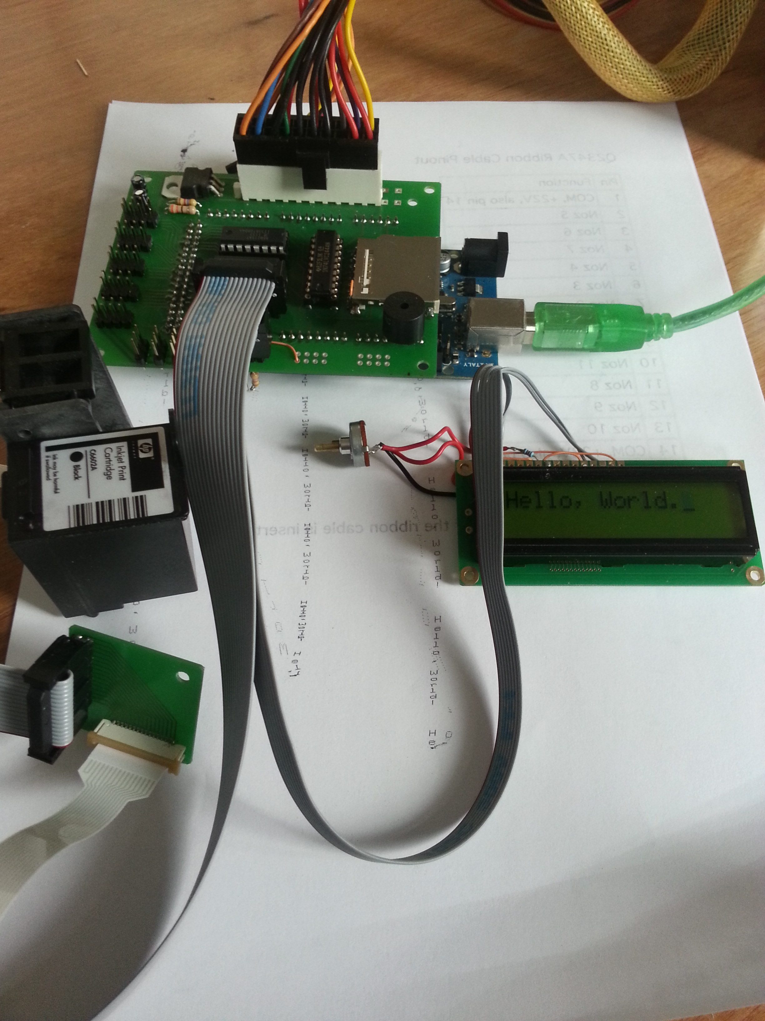
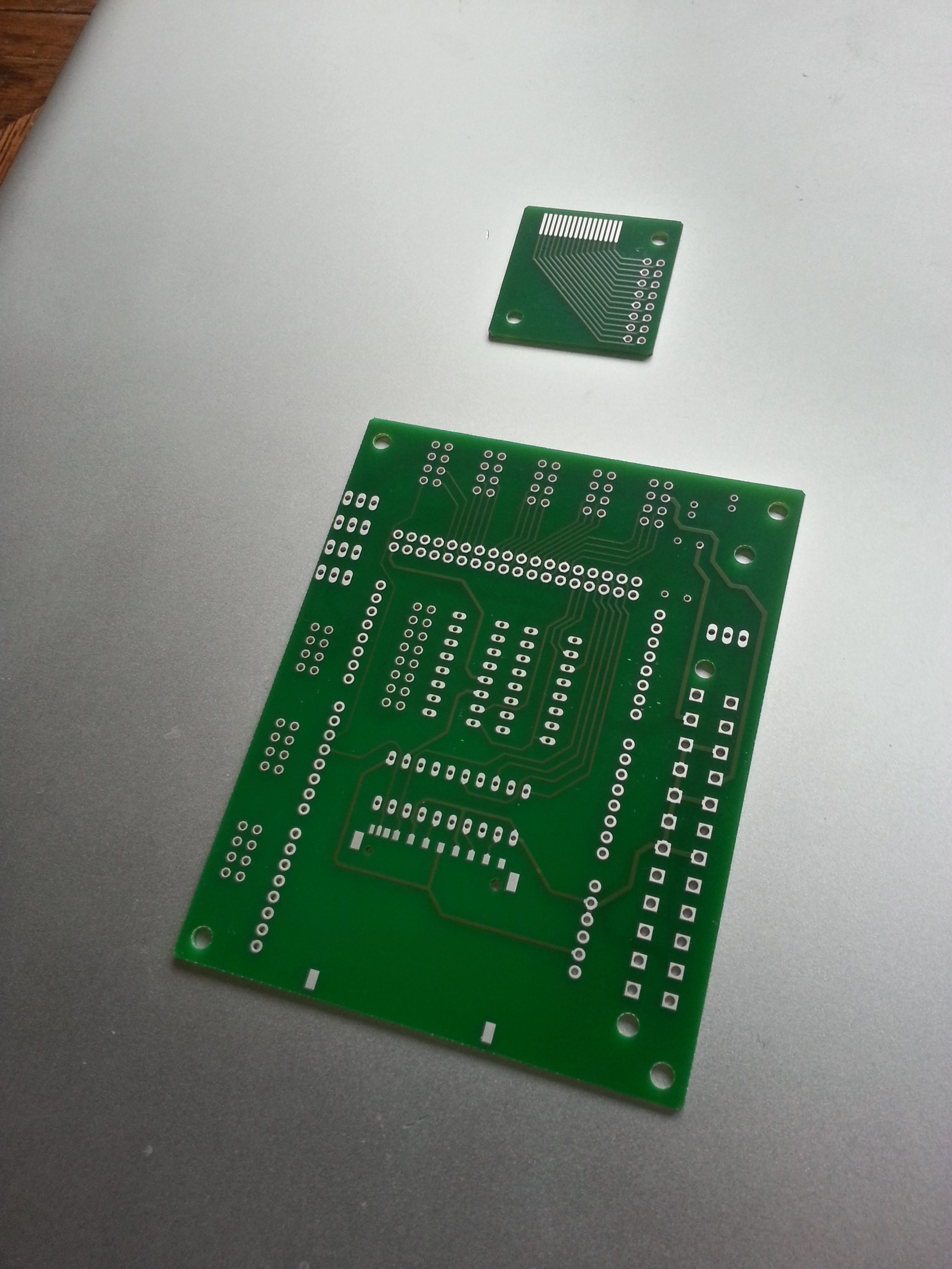
OK, in the mean time, I received the PCBs for my Arduino Mega breakout board.It’s a collection of headers that go to the steppers and come from the end stops, an i2c header for a display, a full size SD card holder with level converter, and of course the darlington array to control the ink head nozzles. Everything is Through-Hole for simple soldering.
And to my own surprise, everything just works! The PC Power Suplly connects nicely and runs everything from Arduino to steppers to ink head. The X and Y motors are connected and work fine. And of course the Ink Head works as well. So I managed to print a few lines of text onto a paper that I taped on the build chamber.
I also managed to finally find the missing 2.5mm bolts to mount the Z Drives, but I am unhappy with it. The torque will eventually rip the mounts out.
Note: PCB needs room for beeper, status LED, reset switch, i2c pullups, smaller PC plug. Z Motor mount needs to be reworked.
Mar 6th 2013: Moved. Electronics.
Horray. I have an internet connection again. The friendly man from the Telekom drilled a few holes and mounted two little beige boxes, and I am online again.
After carefully weighing my choices, I ended up redesigning the ink cartridge driver board as well. My version requires four CPU pins and no extra power supply using only two chips (or one in SMD). I received the chips today, and I will hopefully solder and test the board tomorrow.
Mar 1st 2013: Moving, and Moving On
In case you wondered: I moved to another city and we are not online yet. Still, a lot happened around the machine. No pictures though for the lack of bandwidth.
So first of all, I redesigned the entire moving assembly of the machine. I threw out all the nuts and bolts and glued the parts instead. But a lot more needed to be changed, so instead of fixing here and there, I started from scratch. The original design must have been for different stepper motors. Everything was interfering with everything else. The roller motor scratched on the Y rod. The X motor had different mounting holes and would not fit in the space alotted. The Y motor did not fit either.
In the new setup, I also redesigned the X carriage to match the cartridge holder. The new Y carriages are much more sturdy, and the gantry no longer collapses under the pull of the belt tightener – which I redesigned as well.
I kept the body (for now) and assembled everything. All motors, pulleys, and belts are mounted and connected and work sufficiently well.
The stepper drivers are connected, but not yet mounted. The end stops work with the microcontroller, but are not mounted either. I put an SD card reader together on a strip board that I assembled and tested this afternoon.
Feb 19th 2013: Slow Progress
Today was a busy day – not for Pwdr though. I did have time to assemble the ink carrier and discovered an issue that will throw me back. The wood I am using is too soft in the 4mm variant. Tightening the screws squishes the wood and nothing fits right anymore.
There is another issue: some steppers don;t fit. This may be due to false transfer to parametric files, or because the steppers are a different than the original ones.
In any case I have to redesign the 4mm oarts to make the steppers fit better and to configure them for glueing instead of bolting together. To make everything correct (the German gene), I will have to enter all external parts used into teh CAD system
Feb 18th 2013: Back at Work
I managed to sand down one piston to fit into the box. The box is too high and the lead screw does not push the piston all the way to the top. This need to be fixed for the next version for easy part removal and cleaning.
I ordered a few more electronic parts, mainly wires and a 3.3V converter for the SD Card socket. Oh, and two new tooth belts as the original ones were much too short.
Feb 12th 2013: Arduino and Steppers
Today I had time to play with the Arduino. I ordered the Mega 2560 as mentioned in the BOM, a model that is already pretty outdated agin. Time flies when you’re having fun… .
I hooked up the Arduino with a Dange Shield and an EasyDriver to my Mac and started the Arduino dev environment.
Kudos to the Arduino developers. Everything worked right out of the box and pretty much exactly as described. This is something I am not used to as a software developer 😉 .
So what do we have so far: CPU, buttons, sliders, and a happily turning stepper motor. Still ahead though is the SD card interface (I am somewhat reluctant to buy a shield for such a minor layout), more buttons, a display (the good old 2×16 standard), end stops, and of course the ink cartridge control.
This particular cartridge fires 12 nozzles, one at a time at 5us per nozzle. Using a 74154, we can select each nozzle using only 4 pins plus one pin to enable the brint head (the output must be inverted!). We can further reduce the number of pins by using a shift register, shifting out the pattern, or even just shifting out a 4 bit number (3 pins).
Feb 5th 2013: Building a Piston
Click here to see how the pistons are built.
Click here to see how the body is built.
Feb 4th 2013: Cleaning parts
You saw the parts right after they came fro the laser in the picture above. The scorching comes from the laser buring the glue between the layers of wood. The picture on the left shows a sample part after and before cleaning with sand paper. I use my lunch break to clean a few of the parts.
Customs let my stepper controllers through. Hooray! The stepper motors will be sent tomorrow, which will then complete all my orders so far. I know already that I will need longer timing belts, but I won’t order them until I know exactly how long.
Feb 3rd 2013: Design decissions
Traveling by train is great. I used the time to draw a bunch of plans for a next version, including gutters, parts distribution, a removable controller, a powder collection box, and removable ink tanks. A man can dream, right?
My other research was more about the HP45 cartridges. I found flexible PCBs in the Farnell catalog, and I wonder if it would be possible to create a daughterboard for five-cartridge ink head X-carriage, as they are unavailable from HP.
Feb 2nd 2013: New Stepper Drivers ordered.
Being a very impatient person, I decided to look for different stepper drivers instead of the SparkFun EasyDrivers. I found the Pololu A4988 drivers at Watterott which are in stock and have even better characteristics than the EasyDrivers. The 16 microstep setting may prove invaluable since my belt gears have a larger circumference.
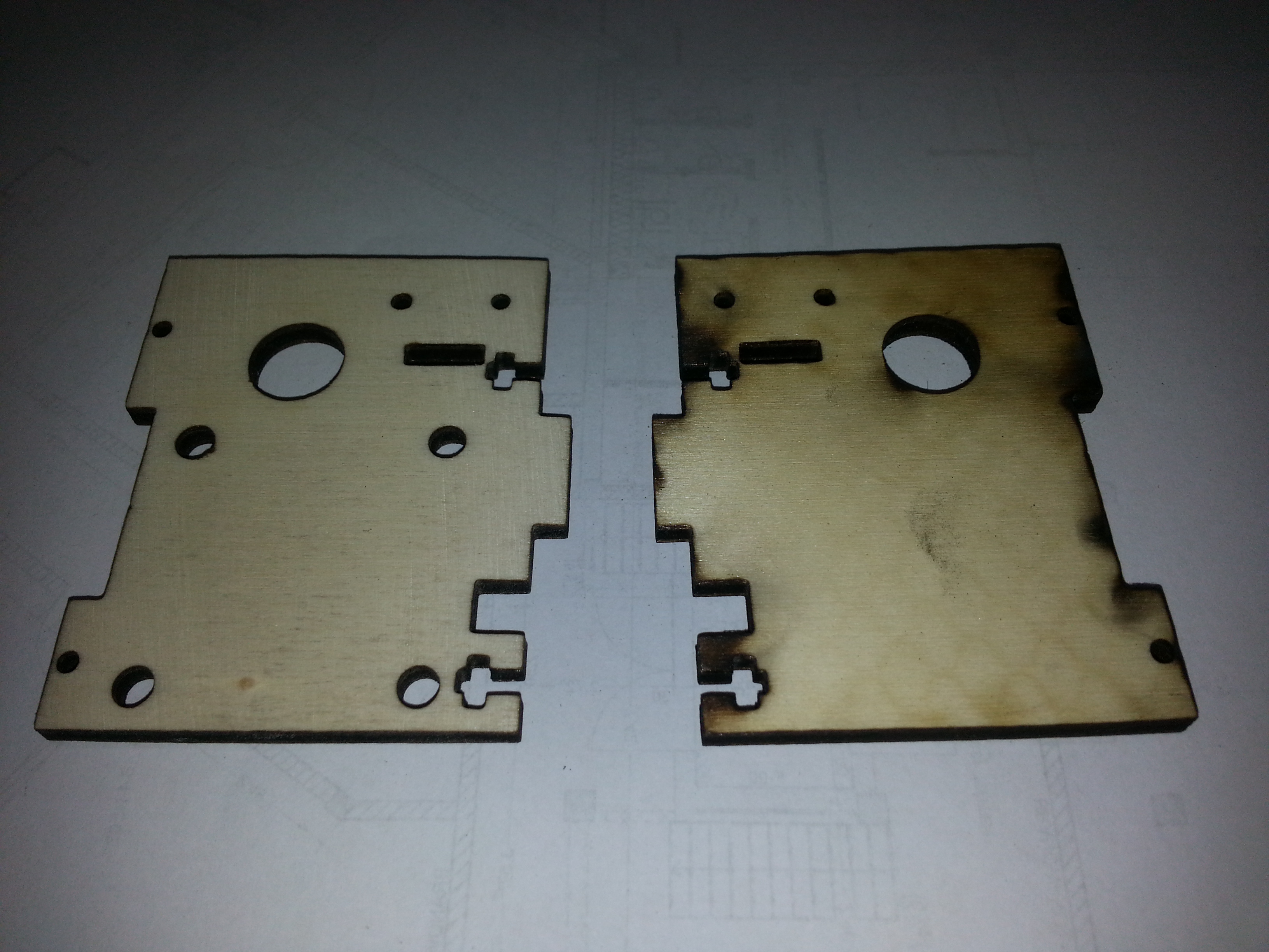
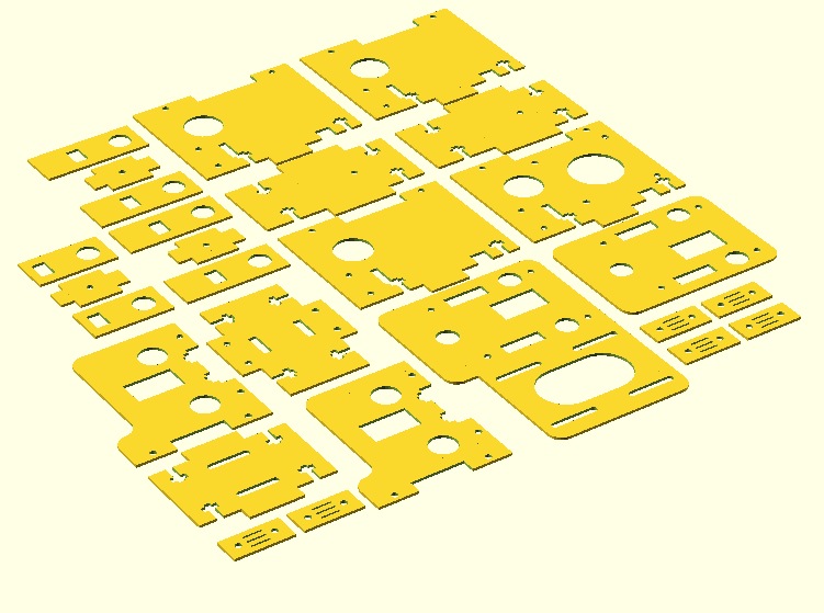
Feb 1st 2013: Laser Cut Parts
WIth a little extra time on my hands, I managed to laser-cut all required parts. The picture shows the results just as they come from the machine. They still need to be cleaned and sanded. I used the wrong kind of wood: the glue is giving the laser a problem, resulting in a slow cut and charring. With a different sort of wood, this could be much reduced. Taping off the back will eliminate the smoke residue (next time).
Acyllics don’t have this problem.
This is the file I used. My beam radius is 0.36mm. I set my cut offset to 0.20mm, plust the 0.18mm offeset as mentioned in the file.
- 1: Case Front SIde
- 2: Case Back Side with electronics compartment
- 3+4: Left and Right Side of Case, also the outer hopper walls
- 5: Hopper Floor – this is where the Z steppers are mounted
- 6: Forward Hopper Wall
- 7: Middle Hopper Wall
- 8: Back Hopper Wall
- 9: Electronics Compartment Lower and Upper Plate
- 10: Hopper Wall Mounting Bars
- 11: Piston Floor – the powder goes on top of this; cover the surface with sand paper
- 12: Piston Bottom Plate – mount the lead screw nut here
- 13: Piston Sides
- 14-16: Left Y Carriage with roller motor
- 18-21: Right Y Carriage with X axis motor
- 22-25: X carriage – mount the ink head on part 25
- 26: Belt Holders for 15, 17, 19, 21, and 24
- 27: short tensioner for X belt on plate 14
- 28: long tensioners for Y belts on plate 1
Jan 31th 2013: Testing the design

I laser-cut the pieces for the x and y carriages today from 4mm plywood. There were a few minor errors which I fixed right away. Here is the newest file:
Jan 30th 2013: No new part deliveries
Sigh. Of course, the only order from the U.S. (SparkFun) was held up in customs, being confused for a commercial package. I’ll have to fiddle that one out tomorrow.
I test-cut some pieces on the laser today to figure out the beam width (it’s 0.8mm – must replace lens and mirrors, I guess). Now I can calculate the bearing holes for a perfect fit.
I also added order numbers for ink cartridges and carrier assemblies. Seems like some of the stuff is made out of unobtainium. I’ll have to salvage these from old printers. The list is on the last Blog page.
Tonight I managed to get the remaining parts into OpenSCAD and render them out as DXFs. Again, these are still untested, cut at your own risk.
The files are licensed under Creative Commons Attribution-NonCommercial 3.0 Unported License (CC BY-NC 3.0).
Jan 29th 2013: New parts
Electronics arrived in the morning, ink cartiridge and carrier came in the afternoon.
I managed to get the hopper and the piston into OpenSCAD. Five more designs to go and I can laser out the parts. Yay!
Jan 28th 2013: Parametric CAD Files
The material that I will be using for the carriages is only 4mm think instead of 5mm. Instead of reworking the files in QCAD, I programmed the layout in OpenSCAD. OpenSCAD ican create CAD files using parameters. For example, I can change the thickness of my material, and OpenSCAD will adjust all drawings to accomodate for the change, yet producing the same final parts.
Therefore, the first lines of the OpenSCAD file contain a list of parameters that can be changed to reflect the different bearing sizes, bolts, and materials. The file is then rendered and output to DXF.
Here is the file for those who would like to try it out. I have not cut anything yet, so there may be errors in the layout. BTW: this is also great if you can not get any metric material. Just change the first few lines to imperails measurements.
The files are licensed under Creative Commons Attribution-NonCommercial 3.0 Unported License (CC BY-NC 3.0).
- PWDR_X_and_Y_Carriage_006.zip (newer version below!)
- Download OpenSCAD here
Oh, and gears, belts, axes, bushings, and bearings arrived.
Jan 27th 2013: Planned Improvements
Well, it’s the weekend and none of the parts arrived yet. So I decided to make a little list of planned improvements by priority:
Current build:
- LCD, Buttons, and SD card slot
- end stops on X, Y, Z1, and Z2
- all electronics including power supply on one removable panel
- car wash (rubber lip under the ink cartridge, rubber seal to avoid drying out)
Next build:
- high resolution print head (HP45)
- 5 heads (CMYK + clear) or single head (Canon) with five tanks
- wider machine to make room for heads
- gutter to collect overflowing powder
Jan 24th 2013: Ordering Parts
I ordered all required parts today. The original part list contains parts that are not available in Germany or somewhat uncommon, so I changed the BOM and moved to local suppliers whereever possible. I managed to get everything I need, but I will have to modify the CAD files to accomodate the new sizes of the parts.
Here are the major changes:
- acrylic replaced by Birch Plywood for cost reduction
- timing pulleys use T2.5 spacing which is more common, using plastic for cost reduction
- timing belts were not available in the required lengths
- ball bearings have no flange and have a larger diameter
- 10mm prcission shaft replced by aluminum pipes to create the roller
- sleeve bearings have different outer dimensions
- fastening bolts are cylinder head becuase others weren’t available
- 24V power supplu no longer available at Farnell
- I also ordered light sensors to be used as endstops, a display to make debugging easier, and a hand full of push buttons for controlling the machine
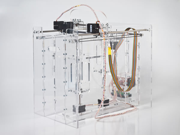
Jan 23rd 2013: First Steps
The first version of the printer will be a close copy of Pwdr as it is described on the page. In later versions, I plan to change the ink cartridge to a higher resolution one, eventually with five colors (CMYK plus transparent).
Today I downloaded all resources from the Pwdr website. I had to convert the SVG files to DXF, so I can laser-cut the part
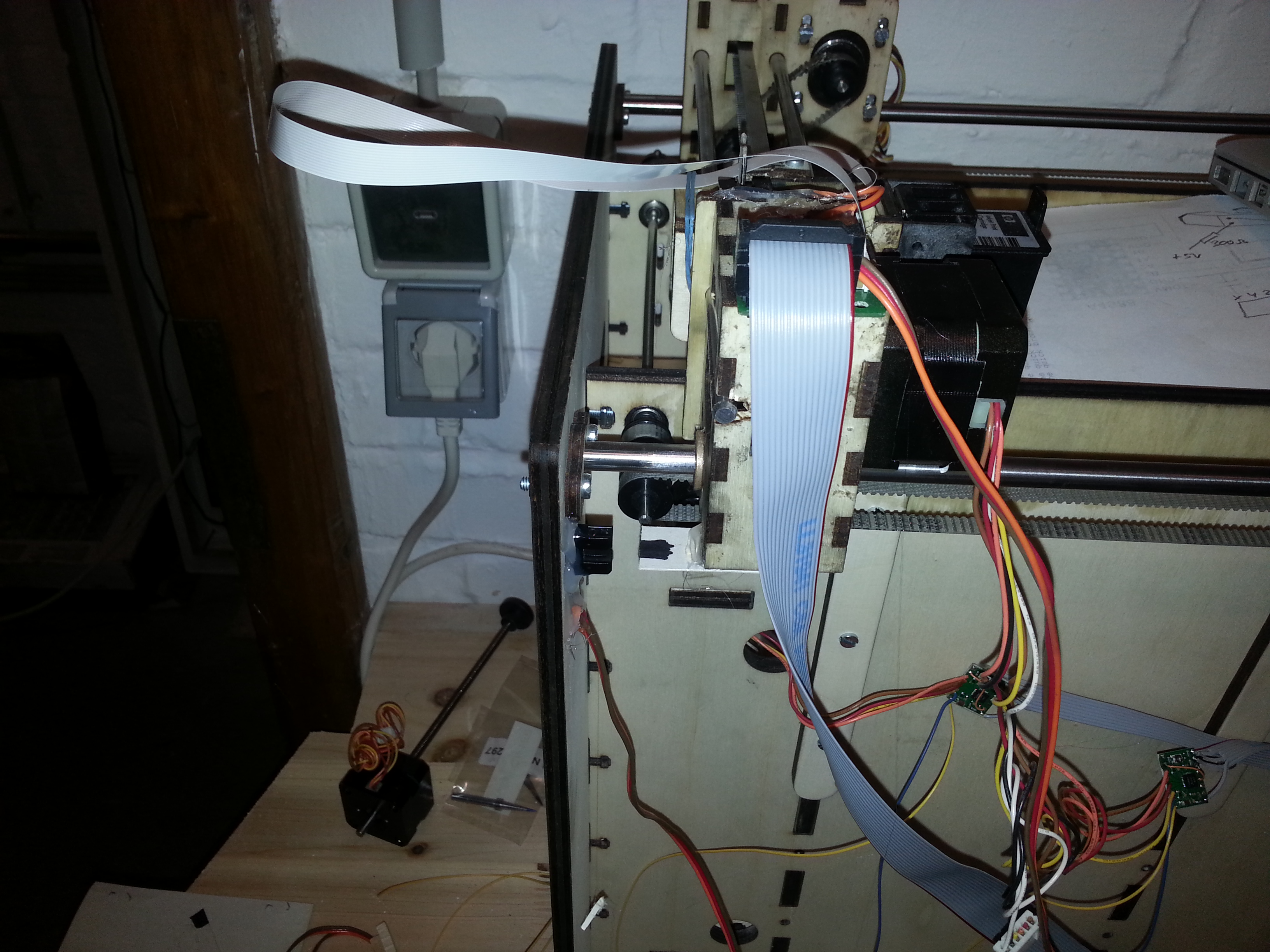
The X axis moves the Ink Cartridge left an right. The cartridge is clicked into a mounting bracket, which in turn is bolted to the X Carriage.
The X Carriage runs on two 6mm steel rods using 6mm brass bushings. The rods are mounted horizontally 32mm apart, 41mm above the powder. It is positioned by a stepper motor on the left side of the Bridge. Parallel to the X axles runs the powder roller. The lower edge of the roller is the surface of the powder. The center is 36mm below the X rod in the middle between rods. The roller is 10mm in diameter, but runs in two 4mm ball bearings. The stepper is located on the right of the Bridge.
- X positioning: 2x6mm rods, 4x6mm brass bushings, 1x10mm roller, 2x4mm ball bearings, 1 stepper with belt, 1 gear, 1 ball bearing
- Roller:: 1x4mm steel axle, 1x10mm roller, 2 ball bearings, 1 stepper with short belt, 2 gears
The Bridge positions the head in the Y direction (back to front). It runs on two 8MM rod in four 8mm bushings. A stepper drives a 4mm axle which then moves two belts. The rods are 270mm apart and 8mm above the powder. The X rods are 33mm above the Y rods
- Y positioning: 2x8mm rods, 4x8mm bushings, 1 stepper, 4 gears, 4 ball bearings, 1 shot belt, 2 long belts
The pistons are positioned with screws.
- Z positioning 2 steppers with screws and nuts, assembly is sliding
Hoper height: 380mm, Y height: 388mm, Y rod 8mm over powder, Y axis 17.5mm under powder
Thoughts
Parts:
- 74LVC244 TTL to 3.3V converter
- Felx circuit Board from Farnell
- Flat Ribbon Cable, connectors (stepper, print head, end stops)
- 100nF cap for SD Card
- I2C control panel
- RobotShop offers a 3.2″ touch screen shield for $33
- LCD03 at http://www.ecse.rpi.edu/courses/CStudio/Lcd03tech.htm provides I2C display plus buttons
Powders and Binders (Resources):
- http://reprap.org/wiki/Powder_Printer_Recipes
- http://forums.reprap.org/read.php?153,11563
- and of course http://open3dp.me.washington.edu
- infusion is the key: http://www.youtube.com/watch?v=kRgKT1otaJw
Case Enhancements:
- reduce material, at least parts 3 and 4 can be half their size
- a space for all power supplies, so I only have an on/off switch and one plug in a non-dusty area
- a control panel with an LCD, a hand full of buttons, and a slot for an SD card or USB stick.
- mounting holes for the recommended electronics boards
- removable electronics board for easy soldering and testing
- a collar around the hoppers, so the powder does not fall all over the place
- a collecting funnel and bin at the front, so the powder is collected after rolling it onto the build pile
- a perfect wire path with a power chain, so the wires don’t interfere or break
- a carrier for a continuous ink supply of all required colors
- a depowder station 😉
- and while we are at redesigning the fuselage, I would either have an outer cover and lid, or I would change some parts, so the machine can be dropped into a plastic or aluminium case for protection.
Memo:
- HP 96dpi: Cartridge C6602A, Carriage assembly Q2347A
- HP45 600dpi: Cartridge 51645AE, Carriage assembly C3540-CARRIAB-R (4 inks only!)
- Canon Pixma MP640 and others: Tanks CLI-521, Head QY6-0072-000, Carriage unit QM3-6893-000
- Continuous Ink System (example): Dauerdrucksystem CKiP4600
- Parts can be harvested from:
- Canon Pixma IP 3600
- Canon Pixma IP 4600
- Canon Pixma IP 4600 X
- Canon Pixma IP 4700
- Canon Pixma MP 540
- Canon Pixma MP 550
- Canon Pixma MP 560
- Canon Pixma MP 620
- Canon Pixma MP 620 B
- Canon Pixma MP 630
- Canon Pixma MP 640
- Canon Pixma MX 860
- Canon Pixma MX 870
Q2347A Ribbon Cable Pinout
| Pin | Alt | Function |
| 1 | 16 | COM, +22V, also pin 14 |
| 2 | 15 | Noz 5 |
| 3 | 14 | Noz 6 |
| 4 | 13 | Noz 7 |
| 5 | 12 | Noz 4 |
| 6 | 11 | Noz 3 |
| 7 | 10 | Noz 2 |
| 8 | 9 | Noz 1 |
| 9 | 8 | Noz 12 |
| 10 | 7 | Noz 11 |
| 11 | 6 | Noz 8 |
| 12 | 5 | Noz 9 |
| 13 | 4 | Noz 10 |
| 14 | 3 | COM, +22V, also pin 1 |
| 15 | 2 | bridge to 16 |
| 16 | 1 | bridge to 15 *1 |
*1: this can be used to check if the ribbon cable is inserted
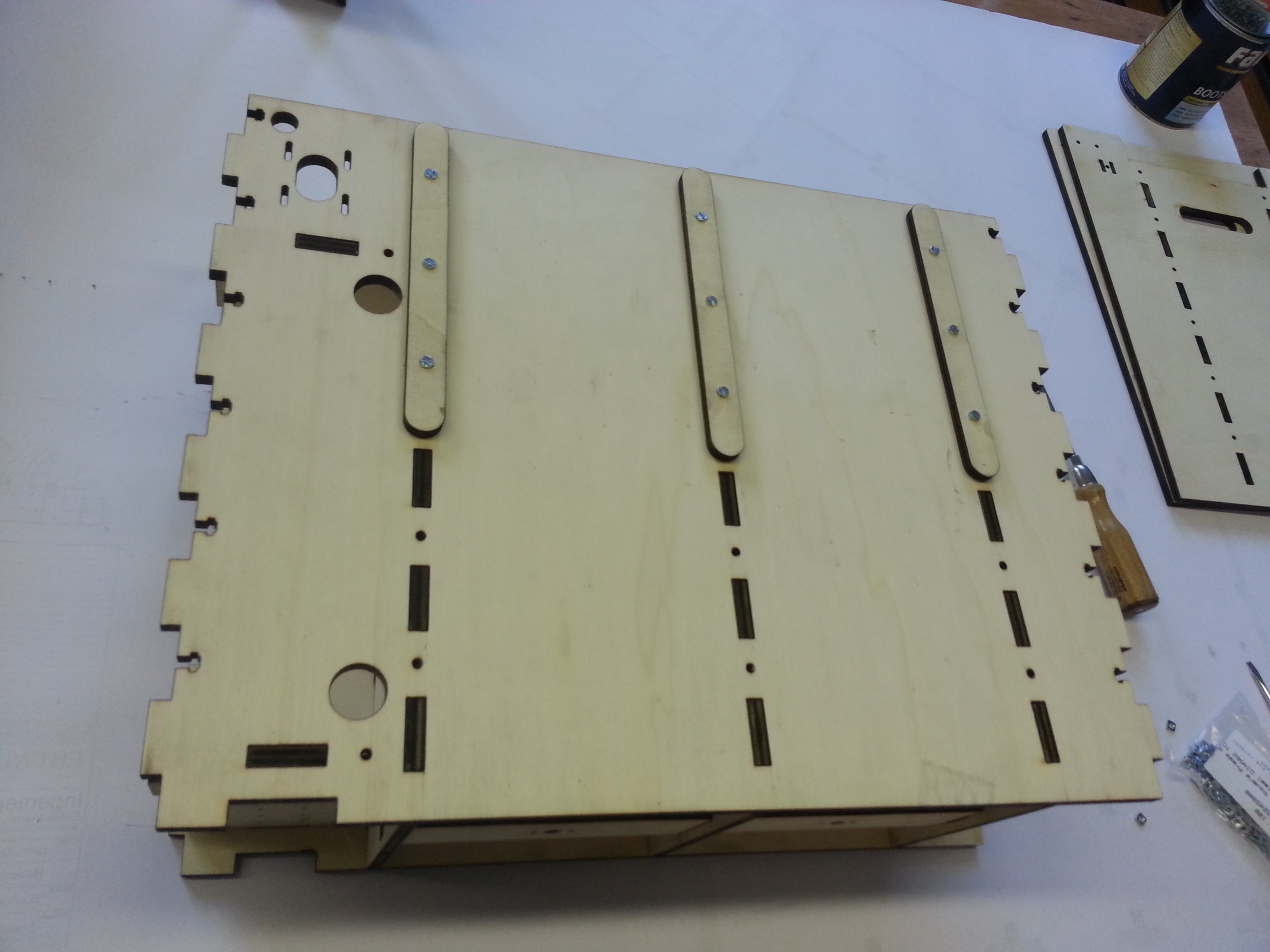
Piston Parts
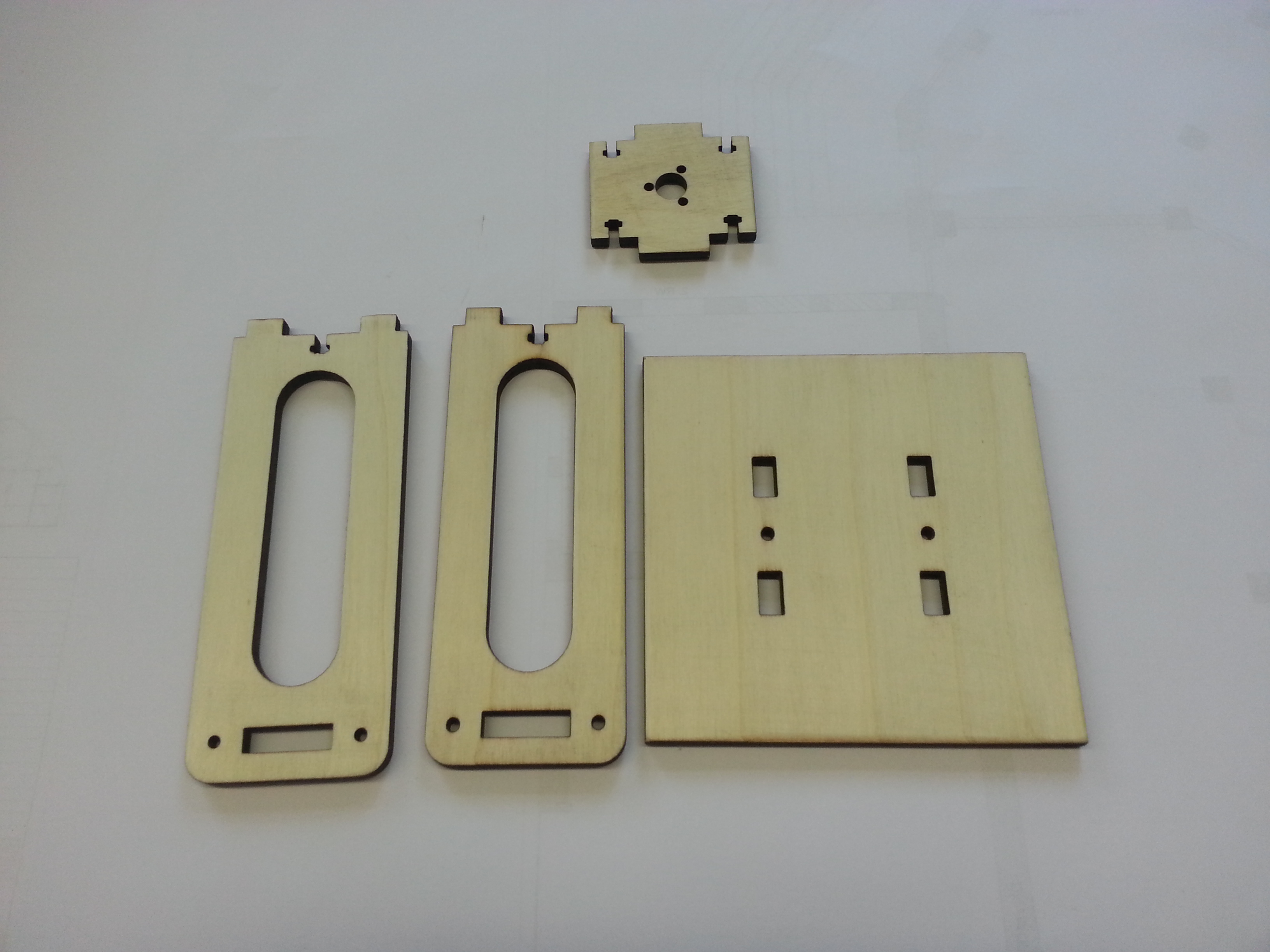
The first part I built today was one of the pistons. It is made from four parts, and it is pretty simple to put together. You will need the piston bottom, two sides, and the platform.
This is where the Square Nuts go
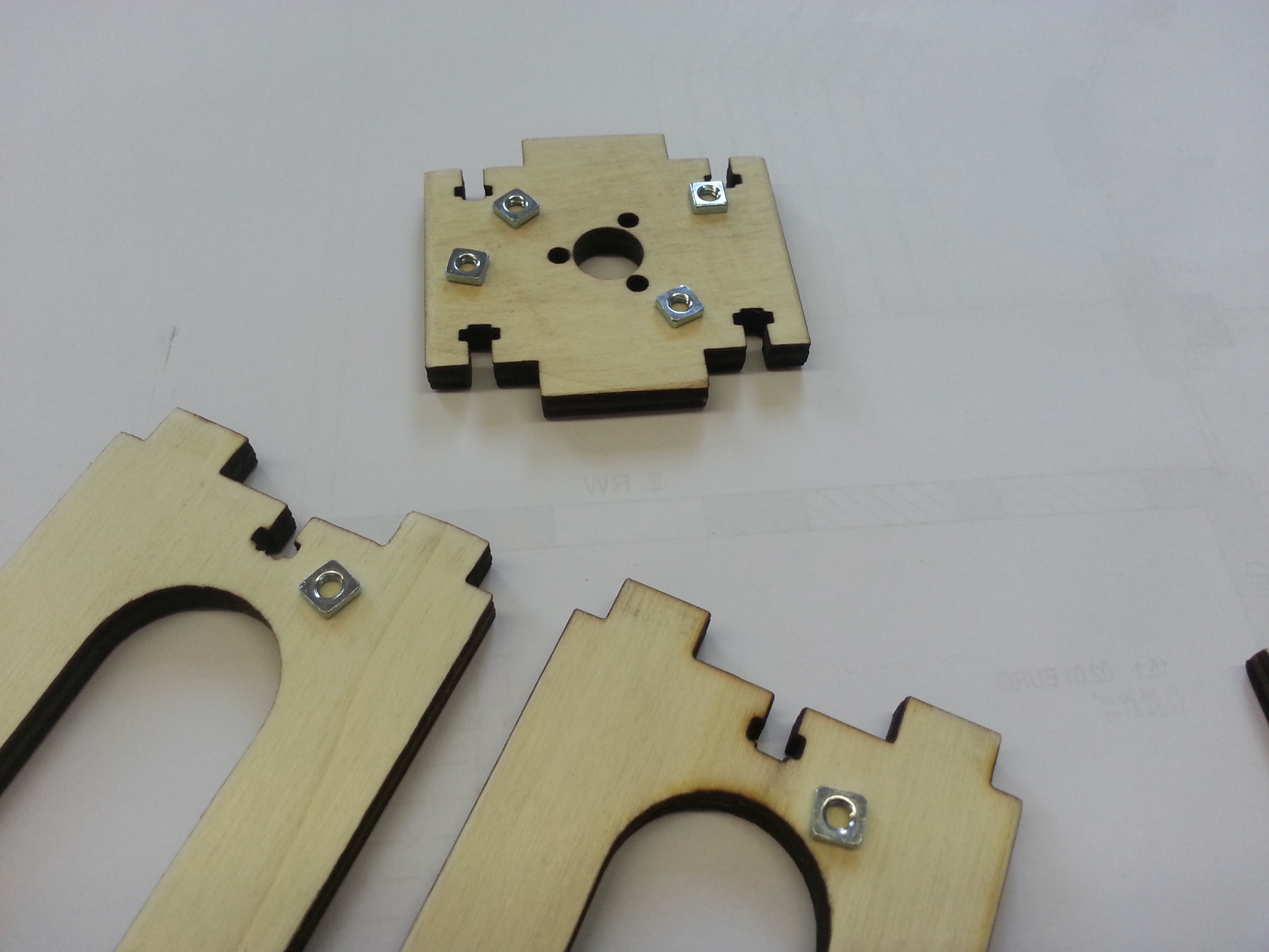
This version of Pwdr is held together by square nuts and cylinder head bolts. Of course you can use hex nuts as well, but they will not fit too well into the cutouts and turn. Grab six M4 square nuts and have them ready to into the slots in the bottom and sides.
Square Nuts in the Hole
The nuts fit somewhat loosely into the cutout (this may change in the next version). Slide them in after putting the parts together and lock them with the 16mm bolt. Now for the bolts, there are two strategies. The correct wya would be to use washers on this soft wood. The easier and almost as effective way is to simply tighten the bolts a bit more than usual until the pull themselves into the wood for a millimeter or so.
Connecting Bottom and Sides
This is pretty straight forward. You need four square nuts and four bolts. The circle and three holes in the bottom are for mounting the lead screw nut. Don’t worry about that one now.
Both Sides Mounted
As you see in the picture, the sides are not truely parallel. The reason is simple: the laser beam is focused through a lens and has a single point of focus. Below the point of focus, the laser beam is conical, and so is the cut that is created. As a result, the cut sides of the bottom part are at a slight angle.
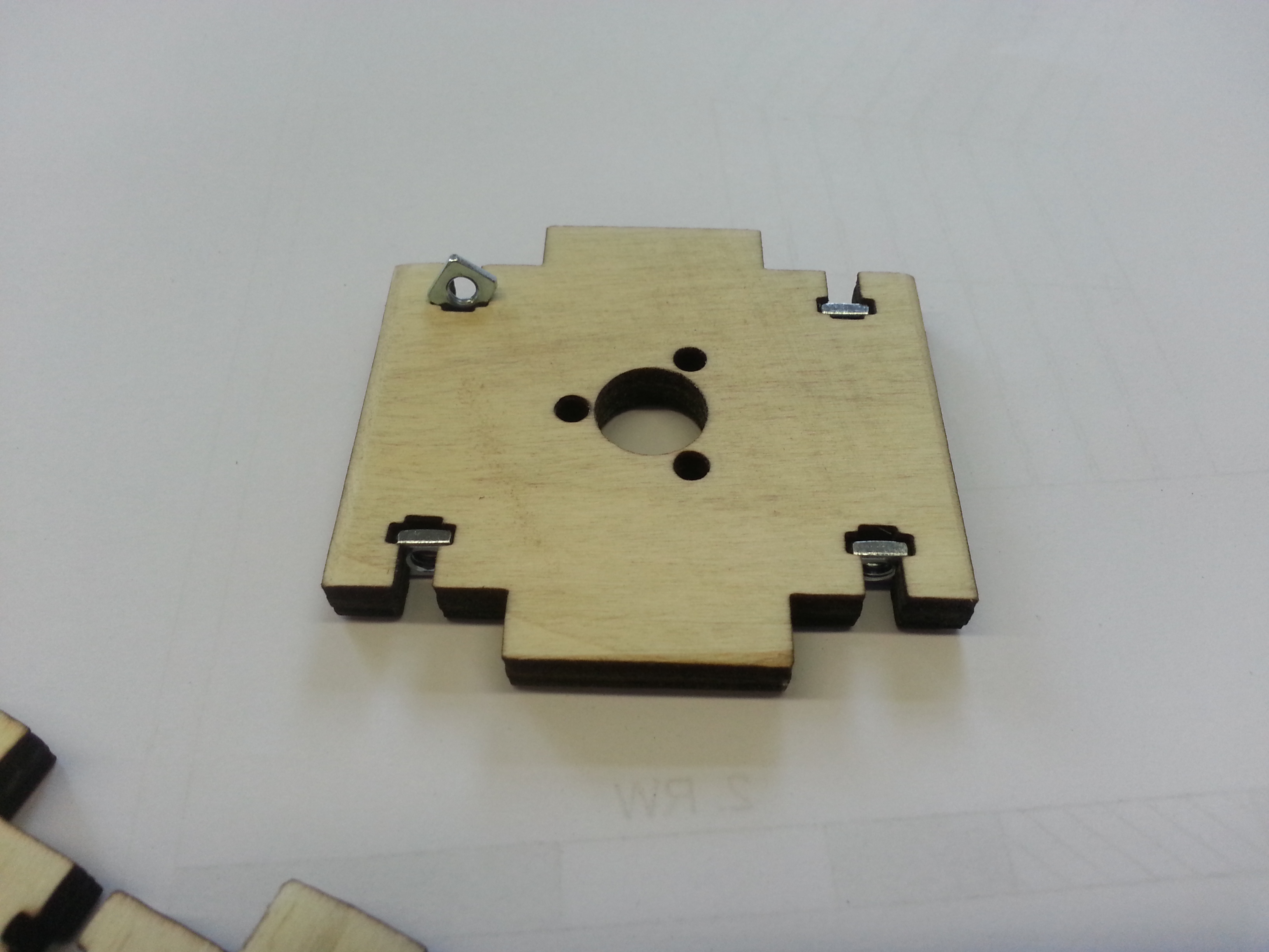
Sinking The Bolt Heads Into The Piston Floor
The piston platform must be flat. For countersunk head bolts in wod, we just tighten the enough. In acrylic material, or with cylinder head screws, we need to manually countersink the holes. There are perfect tools for that. I just used a screw driver.
First Piston Assembled

Here is my first piston. As soon as the motors arrive, I wil mount the lead screw and mount the piston inside the hopper.
After assembling the hoppers, the platform need to be sanded down at the edges to create a tight, but non-blocking fit.
Since we will be using wet binder, I decided to cover the pistons and the insde of the hopper in spar varnish. As a last step, we have to glue sand paper (100 or 60 grit) onto the top of the platform. When spreading a new layer of powder, the sand paper wil keep the previous layers from sliding.
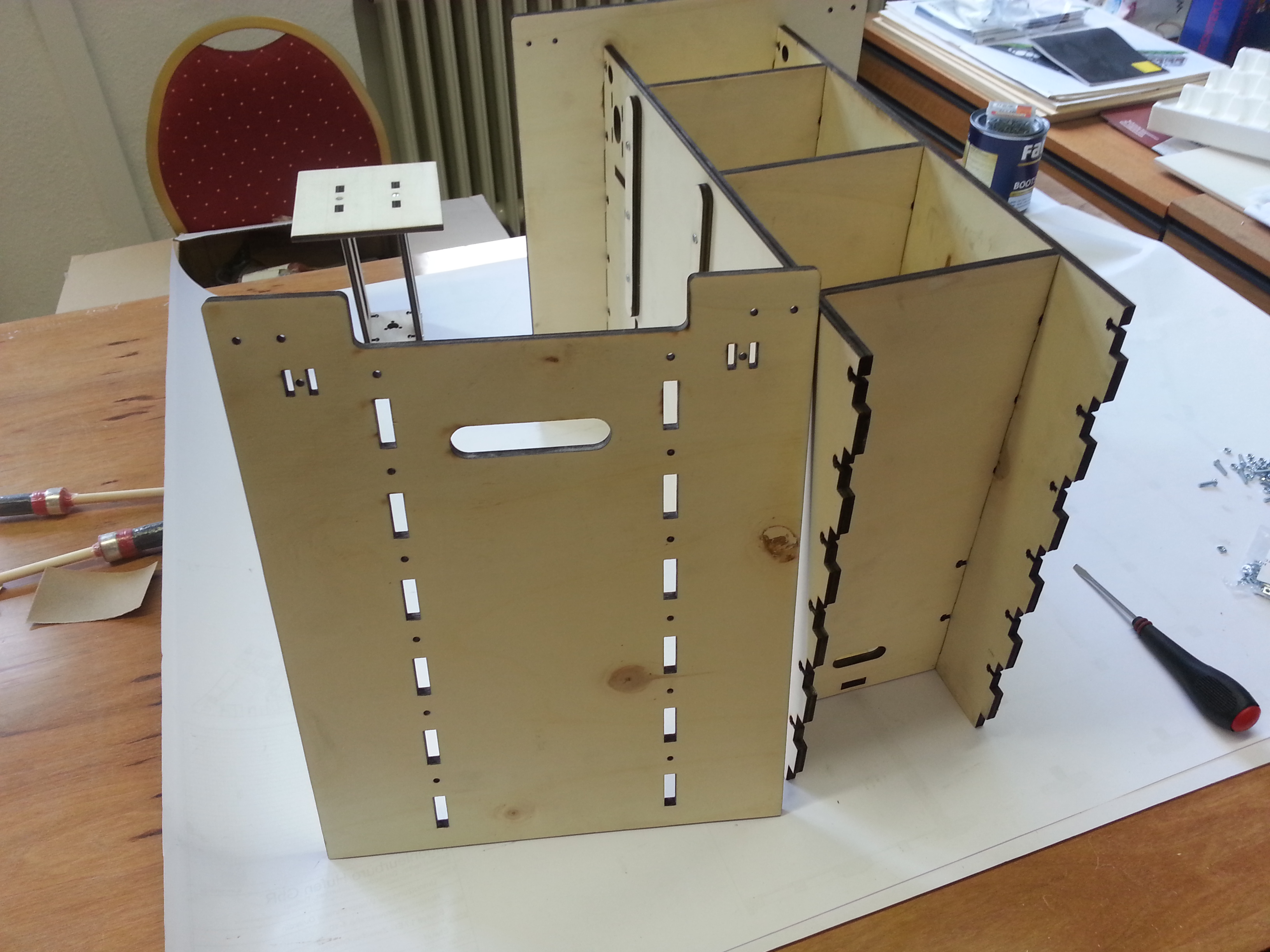
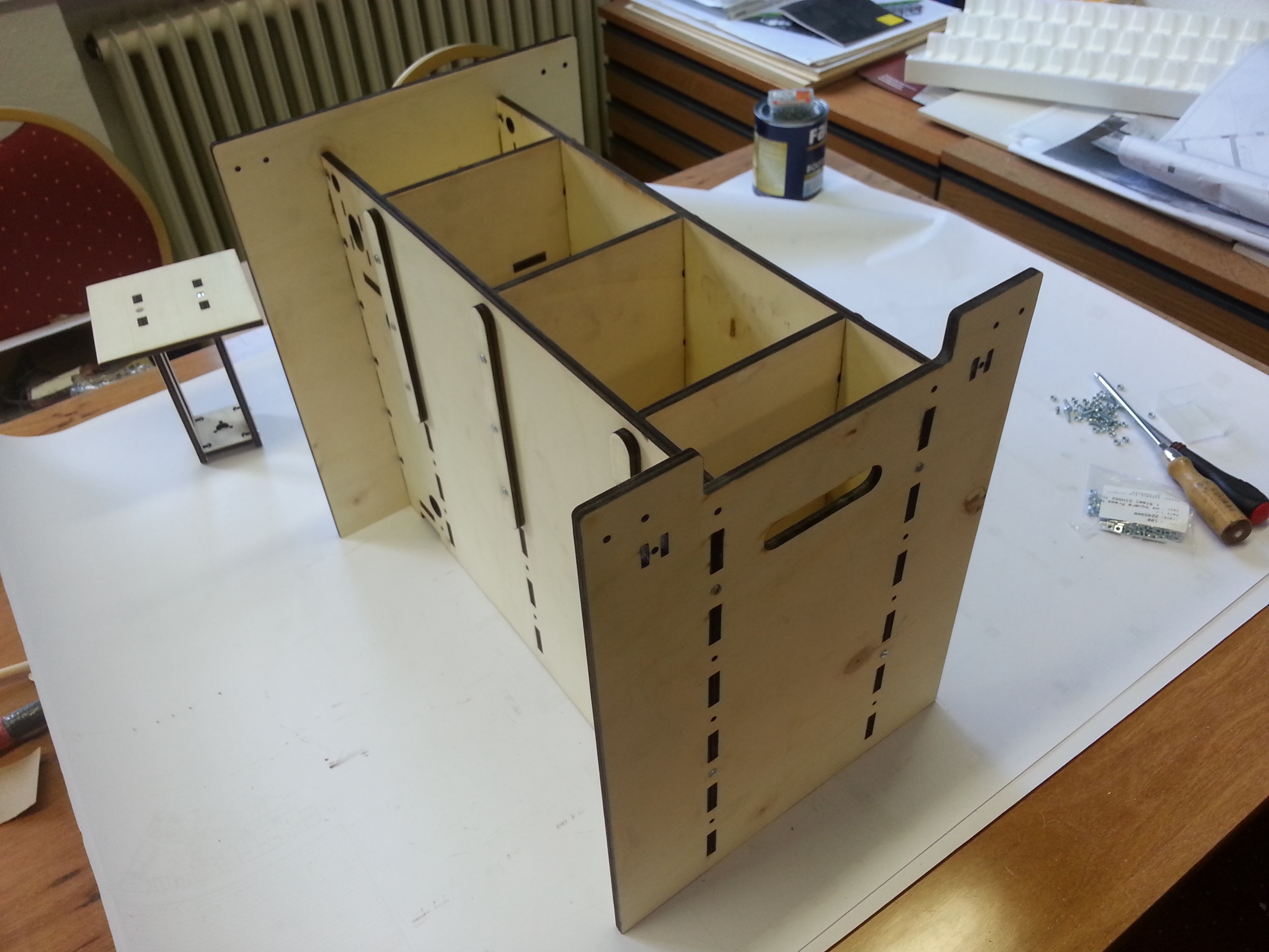
Assembling the Body

Now here we have the hopper walls, the hopper bottom, and the electronics box. We will also need the body sides, the front, the back plate, and the six hopper holders.
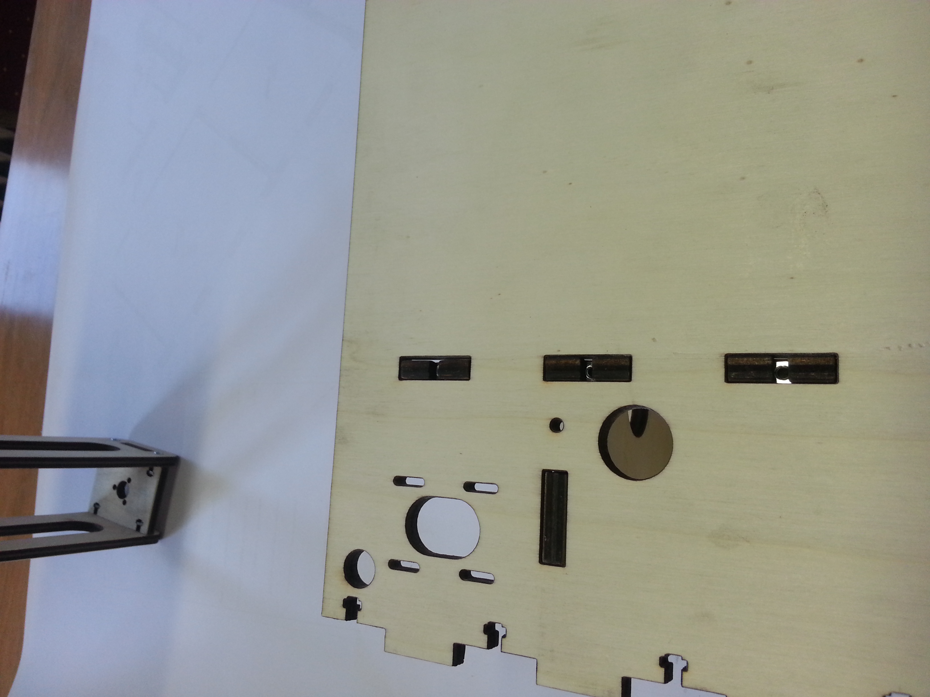
Electronics Compartment
This is a test assembly of the electronics compartment. In the next version, the electronics box will be removable.
Hoper Assembly
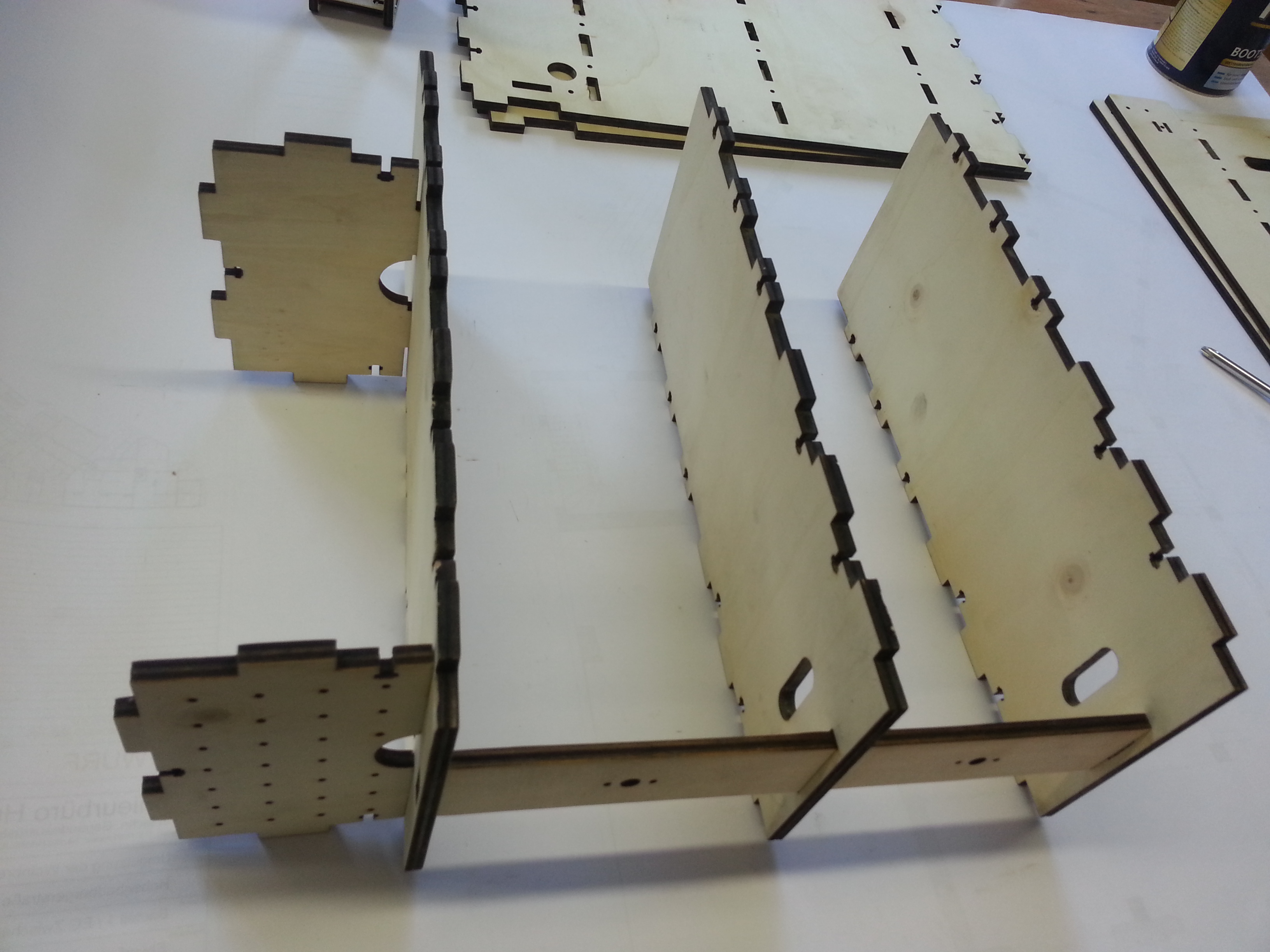
I tested the hopper assembly here. This entire setup can then be dropped into one side, then covered by the other side. Tightening all bolts will put the case quite straight, even i some of the parts are slightly bent by humidity.
Don’t Forget The Hidden Nuts!
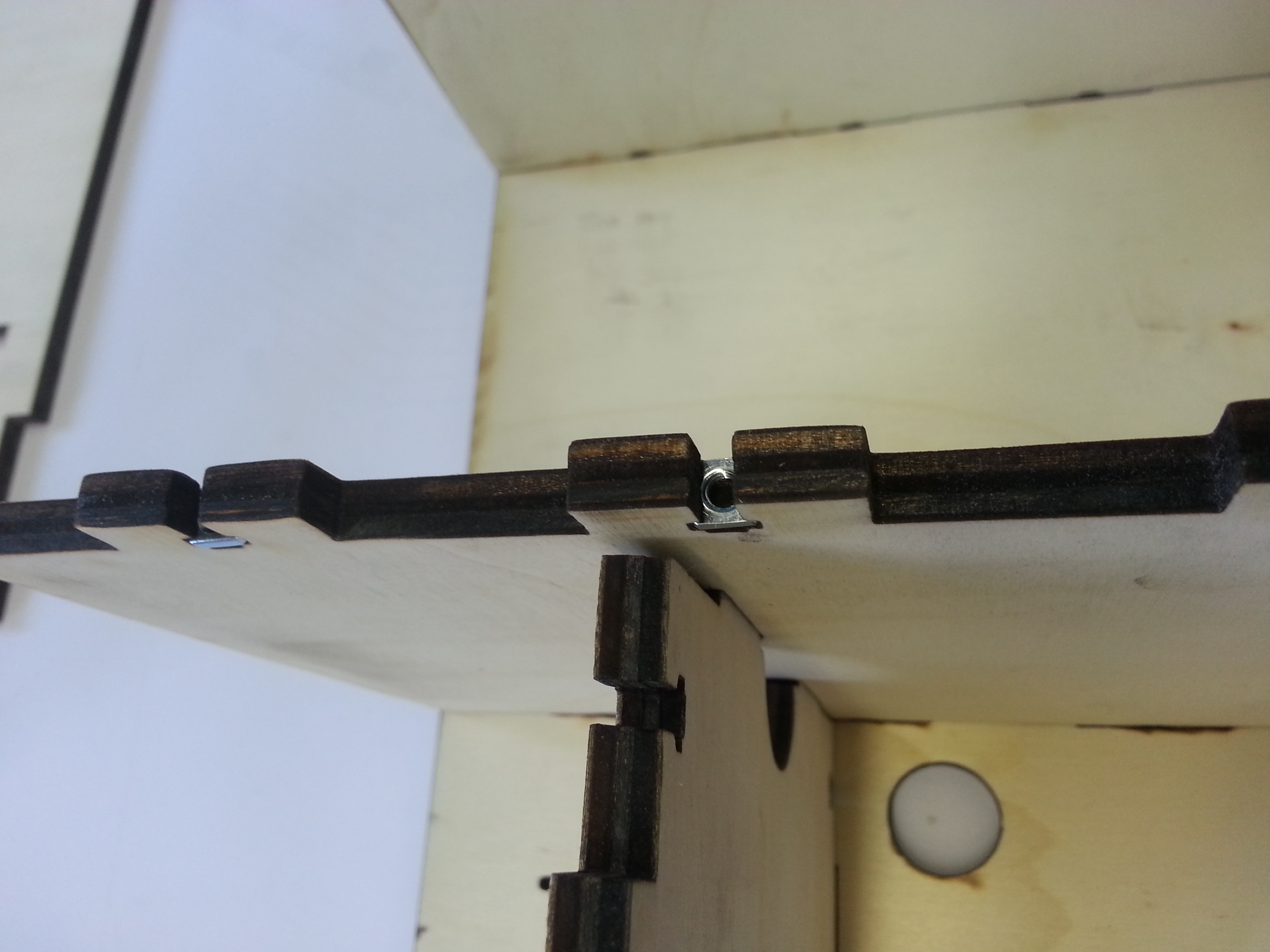
There is a speciality about the hopper sides: the upper set of square nut holes are located on the fingers instead of th slots. The idea is, that the bolts will not interfere with the piston, creating a solid hopper surface inside. So, before dropping the walls into the side, slide the square nuts into the finger holes.
Putting It Together

Allright. I started at the front. The first wall goes in. Don’t lock it yet. It nees to remain movable until all the walls are in.
Z Motors Mount
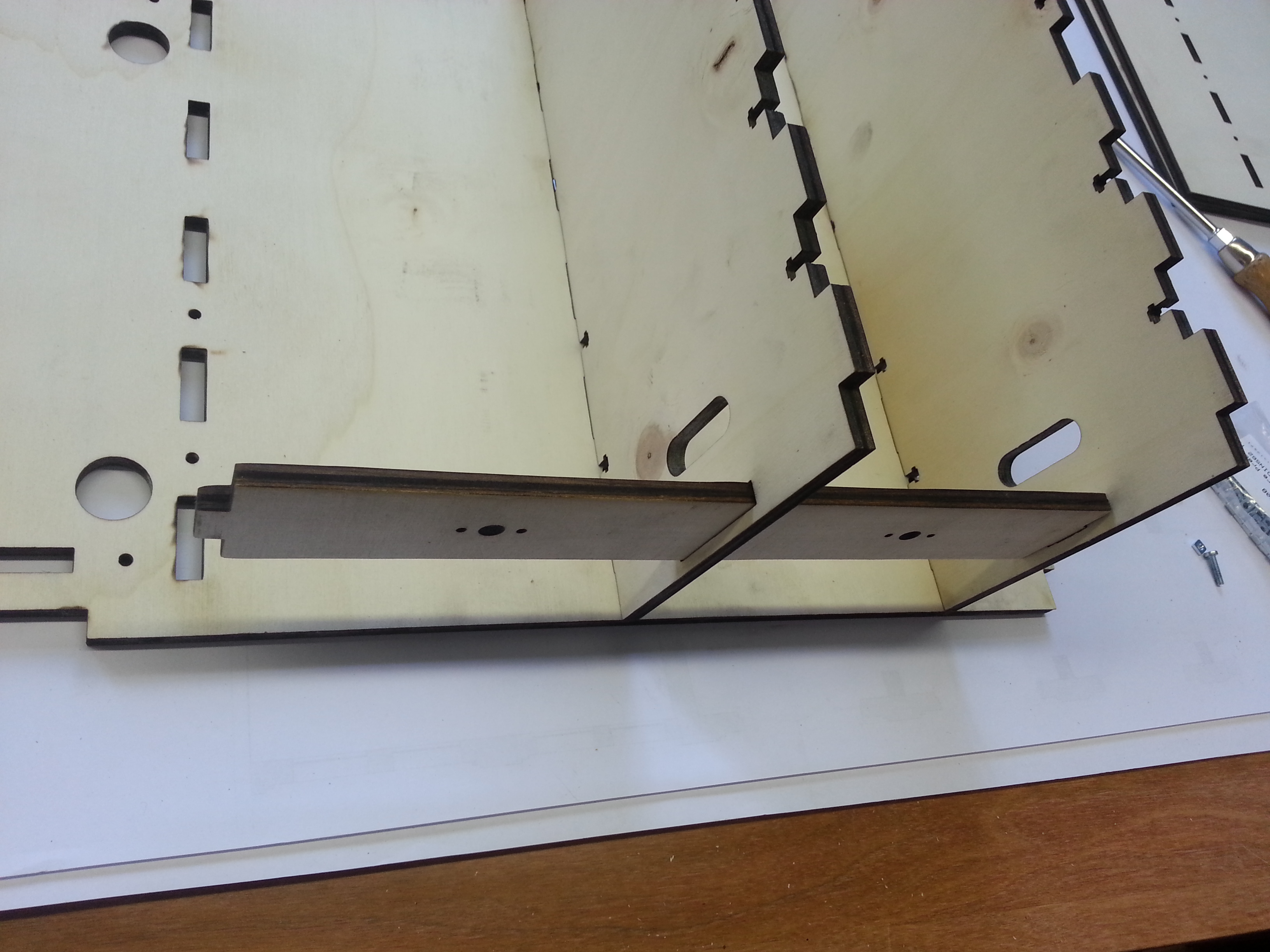
Drop in the middle wall. Now you can slide the motor mount through. It will help stability. The motors can be easily mounted later.
All Walls In

With all walls, the motor mount, and the electronics box interlocking, we drop the entire assemply into the side panel. It only fits one way.
Hidden Nuts
Here is another look at the hidden nuts in the finger joints. It’s easy to see now why they need to be put in before assembling the parts. All other square nuts can be fit after assembly.
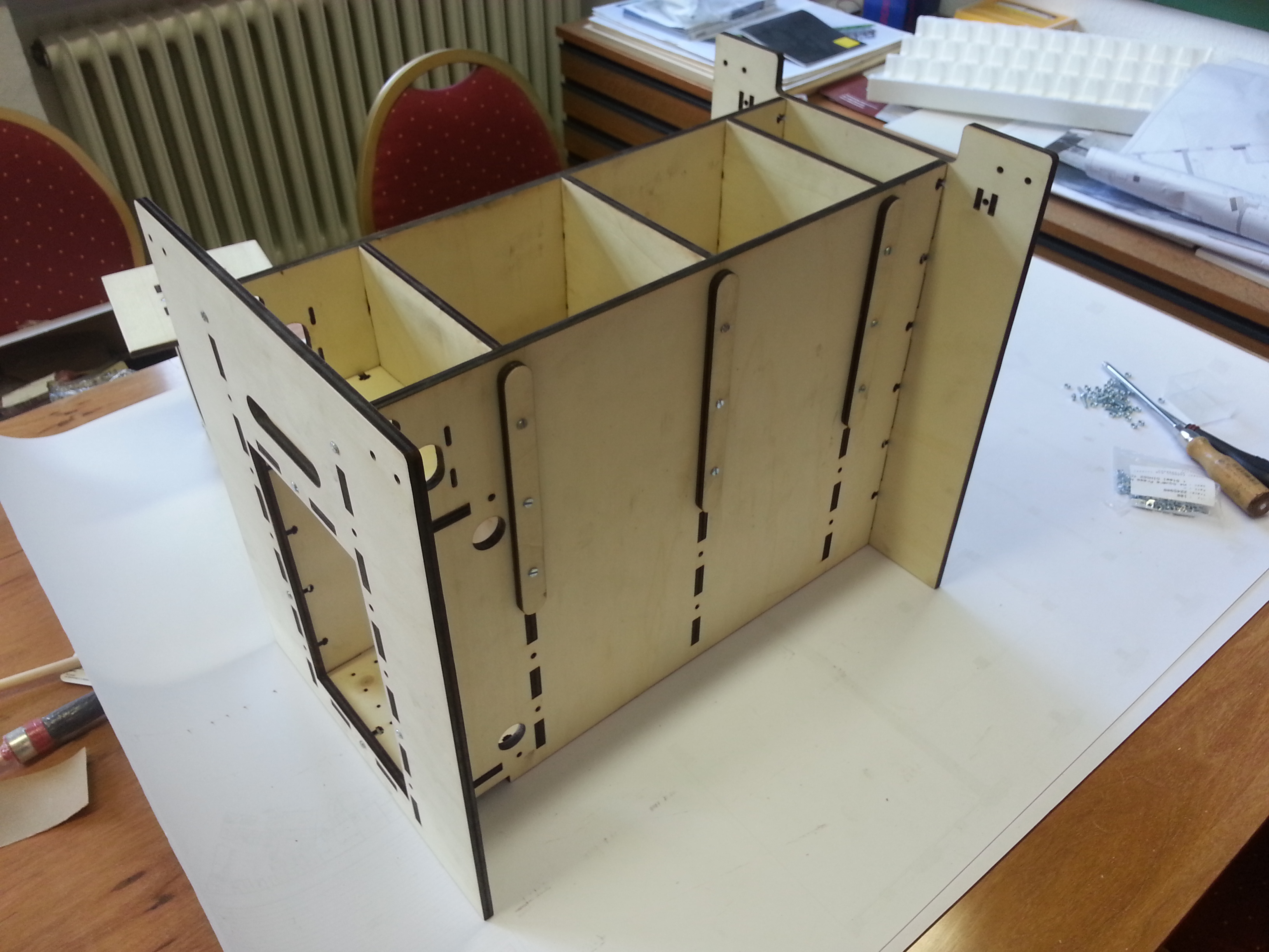
Building the Hoppers
The hopper walls are held using the wall mount bars. Fit the bars and hold them with more M4 16mm bolts. After tightening the bolts on one side, turn the assembly over and mount the other side plate. Tighten the bolts on that one, too.
Electronics Side (Back Cover)
It’s time to mount the back and front sides and give our machine some shape. The back cover is the one with the opening for the electronics. It should fit onto the one end of the assembly. Mount it and lock it with more bolts (At this point, I am running out of bolts. I should have bought the hundred back, not the 50 one).
Front Side
We can mount the front side as well. The front side has a cutout above the handle hole. Again, assemble and bolt it.
Bolted Together
Aaaah. this is how the machine looks assembled. If you still have some time on your hands, you can measure the length of the 8mm Y rods now and cut both to size. They are mounted using the rod holders (which are not neither in my parts pile, nor in my photo, so they are probably not in the CAD file either. Bummer). So instead, let’s enjoy another look…
Side View
… at the main case from another side.
Next, we have to add the bearings, the belt tighteners, and the Y axle with gears and motor.
Thoughts on Firmware
To create a 3D object, the printer will have to follow complex command sequences. The Arduino is great, but not powerful enough to read stl or 3ds files. For that, we will have a host software that outputs a file to SD card. Pwdr will read this file from the card and execute the commands given.
The firmware then has to be able to read FAT32 file systems files byte by byte and interprete the commands as they come in.
The firmware also needs to allow the user to do some basic setups, fill powder into the hopper, empty the hooper, home the axes, and, of course, select a file from the SD card.
List of Firmware Commands
I have a rough idea of the commands that the fimrware needs to support.
- minimal command set:
- move x, y, z1, and z2 relative
- fire nozzle pattern (currently 1..12)
- rotate spreader
- simple automatization
- home x, y, z1, z2 (store steps required in register for later use)
- absolute positioning of all axes
- simple user interface
- echo text to display
- wait for OK button
- simple programming
- registers and simple math
- if-then-else
- repeat command
- extended automatization
- read machine condition if available (print head temp, ink level, powder collector level)
- more sensors: lid open, vacuum, temperature, ink levels, etc.
- extended user interface
- manage choices, lists and menu selections
- assign jump vectors to buttons
- extended programming
- function calls
- local variables
- interrupt vectors for buttons and conditions
- predefined functions for machine type (add powder, change print head, … )
List of Firmware Functions
Again, this is just acollection of spontaneous ideas of what the machine should be able to do at different levels:
- level 0
- test all motors and sensors
- firmware knows machine configuration (hopper size, step widths on all axes, ink system)
- level 1 (SD card, one button needed)
- wait for SD card
- interprete script from file “run.pdr” as soon as the card is found
- stop/abort button
- level 2 (more buttons)
- user can move hoppers individually up and down
- trigger a powder spread (manual home position)
- level 3 (end stops needed)
- find absolute position of all axes
- restore hopper positions
- store hopper positions in non-volatile RAM
- level 4 (better SD card support, buttons, display)
- choose file from SD card via display
- test patterns, roller tests, powder tests, etc.
- update firmware from SD card
List of Software Functions
It is impossible to have the Arduino slice large STL or 3DS files. A PC software needs to do that and generate the pdr file. Here are some features that come to mind:
- supported file formats
- .stl (industry standard, but monchrome)
- .3ds (ages old and easily read, but quite limited, full color, but textures not inside the file!)
- .vrml (as old as 3ds, a bit less limited, textures can be part of file)
- .dae (Collada, well supported, few limitations, extendable, hard to read)
- slicer
- create slices for binder distribution
- add color information as an outside shell if required
- handle non-manifold objects gracefully
- find problematic locations (thin walls, non-manifold bodies, overlaps) and show to user
- database
- maintain a database of available machines and their features
- maintain a database of powder/binder combinations and their requirements for the perfect print
- combining both databases should create the best possible results for a machine/powder/binder setup
- generate test patterns (but also see firmware!)
- pattern to find thinnest and thickest layer heights for powder
- pattern to find best binder amount for powder
- pattern to align colors
- strategical patterns: reduce bleeding, reduce warping, support structures, etc
Firmware Command List
This is the list of binary commands.
| # | Command | Note |
| frequently used commands (1 byte) | ||
| 0 | no operation | does nothing, can be used to align bytes or mark the end of strings |
| 1 | fire pattern | fire a pattern from the binder cartridge and advance to the next firing position |
| 2 | cFire pattern | the next fire command will also fire this pattern on cyan |
| 3 | mFire pattern | the next fire command will also fire this pattern on magenta |
| 4 | yFire pattern | the next fire command will also fire this pattern on yellow |
| 5 | bFire pattern | the next fire command will also fire this pattern on black |
| less often used commands (2 bytes) | ||
| 128 | new line | formatting helper: start a new line in the source code |
| 129 | annotation text | add an annotation in the source code |
| 130 | debug text | output debugging information through the terminal |
| 131 | cls | clear display |
| 132 | cln lineNo | clear a line in the display |
| 133 | display text | display a line of text in the display |
| 134 | displayAt x, y, text | display text in the display (0, 0 is top left) |
| 135 | print text | print some text at the current position using the black ink cartridge |
| 136 | motorOff motormap | switch one or more motors off (stepper driver goes into sleep mode) |
| 137 | motorOn motormap | switch one or more motors on; if any was off, this causes a delay |
| 138 | fireNozzle cartridge, nozzle | fire a single nozzle on the specified cartridge |
| 139 | beep freq, duration | give an audible warning |
| 140 | blip | give a short audible warning |
| motor movement | ||
| 144 | xGoto absPos | move x to an absolute position |
| 145 | xMove relsteps | move x by a positive or negative number of steps |
| 146 | xHome maxsteps | move x to the endstop and reset counter |
| 147 | yGoto absPos | move y to an absolute position |
| 148 | yMove relsteps | move y by a positive or negative number of steps |
| 149 | yHome maxsteps | move y to the endstop and reset counter |
| 150 | z1Goto absPos | move z1 to an absolute position |
| 151 | z1Move relsteps | move z1 by a positive or negative number of steps |
| 152 | z1Home maxsteps | move z1 to the endstop and reset counter |
| 153 | z2Goto absPos | move z2 to an absolute position |
| 154 | z2Move relsteps | move z2 by a positive or negative number of steps |
| 155 | z2Home maxsteps | move z2 to the endstop and reset counter |
| 156 | rStart speed | start the roller at the specified speed |
| 157 | rStop | stop the roller |
| flow control | ||
| 160 | delay mSec | delay execution by n milli seconds |
| 161 | repeat n | repeat the next fire command n times |
| 162 | seek pos | move execution of this file to a new position |
| 163 | waitForButton buttonmap | don’t do anything until a button is pressed |
| 164 | onButtonSeek button, pos | if the given button was pressed during the last wait, skip to that program position |
| settings | ||
| 192 | setFireRepeat n | sets the number of ink drops per fire command per nozzle |
| 193 | setFireAdvance n | sets the number of steps that the head advances in y after firing |
| 194 | setXSpeed n | set the speed for the next x motion commands |
| 195 | setYSpeed n | set the speed for the next y motion commands |
| 196 | setZ1Speed n | set the speed for the next z1 motion commands |
| 197 | setZ2Speed n | set the speed for the next z2 motion commands |
| complex commands | ||
| 1024 | spreadPowder layerHeight | spread one layer of powder, advancing z1, but not z2 |
| 1025 | writeConfig | write machine configuration to SD card |
- motormap: 1 = x axis, 2 = y axis, 4 = z1, 8 = z2, 16 = roller
- buttonmap: 1 = ??
Thoughts on Arduino Pin Asignment
This is a list of inputs and outputs that come to mind. I will have to assign the exact pins and decide, which I/O’s will be shifted.
| # | Type | Pins Assigned |
| Inputs | ||
| 1 | x endstop | |
| 1 | y endstop | |
| 1 | z1 endstop | |
| 1 | z2 endstop | |
| 4 | 4×4 button matrix *2 | 20, 21 (I2C) |
| 1 | SD Card (MISO) | 50 (SPI Interface) |
| 1 | Emergency Stop | 19 (Interrupt 4) |
| 9 | ||
| Outputs | ||
| 3 | x stepper (dir, step, enable) *5 | |
| 3 | y stepper (dir, step, enable) *5 | |
| 3 | z1 stepper (dir, step, enable) *5 | |
| 3 | z2 stepper (dir, step, enable) *5 | |
| 2 | roller (step, enable) *1 *5 | |
| 4 | 4×4 button matrix *2 | |
| 12 | ink nozzles *4 | |
| 1 | enable cartridge | |
| 3 | SD Card (SS, MOSI, SCK) *3 | 53, 51, 52 (SPI Interface) |
| 6 | 2×16 LCD (RS, E, D4-7) *3 | 20, 21 (I2C) |
| 40 | ||
| 49 | Arduino Mega has 53 I/O Pins | |
| 2 | serial line for debugging |
- 1: there is no need that this is a stepper, a geared motor with a PWM output would be just fine
- 2: this would be easy to put on an i2c bus, going from 14 pins to 2 (for example “Devantech LCD03”, there are also some nice I2C PWM LED driver chips available from Philips – ya know, for pimpin the machine)
- 3: using the Enable/Chip Select pin, these devices can share pins
- 4: since we only fire one nozzle at a time, we may use a 4 bit decoder, reducing the number of pins from 12 to 4
- 5: we can use a single direction pin, but then we can never position two steppers independently. We can also group the Enable pins into X/Y and Z1/2
- A: the Arduino has interrupts on 2, 3, 18, 19, 20, and 21
- B: all endstops should be within the bytes of a hardware port
Later: lid contact, cartridge temperature, ink level, powder collection level, powder temperature, …
                     LCD + Keyboard
                           |
                          I2C
                           |
                        +---------+
Stepper X ----- 4 ------|         |
Stepper Y ----- 4 ------| Arduino |----- 13 ------ Ink Cartridge
Stepper Z1 ---- 4 ------|         |
Stepper Z2 ---- 4 ------|         |------ 4 ------ SD Card
Roller -------- 2 ------|         |
                        +---------+
                           |
                           2
                           |
                         Debug
|
About Pins and Inks
The Arduino has 53 I/O pins which seems a lot when counting the I/O’s required for Pwdr 0.1, but let’s have a quick look at the HP45 ink cartridges. (UDN2981 8 Ch Source Dirver, ULN2803 8Ch Drain Driver)

We need to control the HP 45 in a matrix. There are 22 adresses and 14 groups, adressing 308 (actually 300) nozzles. We control the cartridge address by address, selecting groups that will fire. So we need five lines to select an address and 14 more to select the groups with the right nozzles. That is 19 pins for one cartridge.
In full color mode, things get more complex. We can stick with five lines for the addresses and keep the cartridges in sync, but we need 5×14 lines for the groups of all five cartridges, requiring 75 pins. Since that is more pins than we have in our Arduino, we will need some smart multiplexing to stay in control. At 5us impulses per nozzle (12 kHz for the entire sequence), this will be tough!
Checking out the CN642A
The CN642A seems to be a viable head for 3D printing. It comes with 5 colors, has CISS retrofits and still seems to use the matrx-to-mosfet connectivity that we know from older HP heads. Here’s some information I found:
- Printers: PhotoSmart: C309a,g,n, C310a, C310a,b (Premium), C410a,f (Premium / Fax), C510a (Estation) / D5400 Serie: D5445 D5460 D5463 D5468 / D7500 Serie: D7560 (CN642A)
- Price: around 50 Euros, but used printers on EBay go for even less
- inks: 5 (CMYK, Gray), Black has a higher capacity
- resolution: 600 x 600 dpi (b&w) / up to 9600 x 2400 dpi (color) (unconfirmed!)
- contacts: 38 pins
- nozzles: one group of four for the colors, one line for high volume black 9same height)
- Docs: http://h10032.www1.hp.com/ctg/Manual/c01659847.pdf
Reset: On, unplug, press and hold # and 6, plug in, hold 10 seconds.