After a long break, I found some time to finally build the gas pumps displays for my electric charging station. I used the pick’n’place machine and the oven yesterday to solder the SMD components. In the evening, I managed to hand solder the jumpers, the displays, and the CPU (Arduino Nano).
Today, I extended the 4-digit boards by another digit and hooked everything up. I cut two cases in the laser cutter and test-assembled everything. So far, it’s all working. I hope I will have some time tomorrow the complete and thoroughly test displays.
Placing SMD parts for soldering.
28 7-segment displays on 10 boards. Down in the left corner is the Arduino Nano that will control the display by receiving commands from a Raspberry Pi via USB.
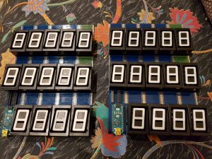
The PCBs are connected through flat ribbon.

Every 7-segment display is controlled by a NCV7708B 6-port H-Bridge. Four of the electromagnets share 3 H-Bridges, decoded by diodes, allowing me to control 7 segments with 6 bridges sequentially.
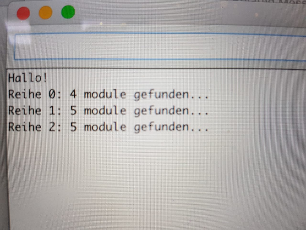
The NCV7708B is controlled via SPI. Every line of displays uses its own software SPI bus. The CPU can calculate the number of modules connected in series by pushing a special command through the BUS. By counting the commands until the first command is received again, we know how many displays are in each row.
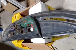
And here are the parts that carry the boards and display. All that fits into a neat little metal case with a transparent front, showing the liters, the total amount due, and the price per liter in Deutschmark. I guess I will have to update that to kWh, Euros, and Euros per kWh 😉 .

Done for today. Tomorrow, I will connect the 24V volt supply and flip all the tabs and make sure that everything works. I know I will need some additional cpas in the 24V and 5V line as well.